Via the SERCOS® fiber optic ring network, the TSX CSY 84/164 :
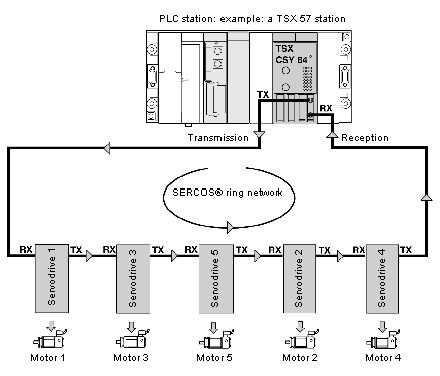
The diagram below shows an example of a configuration of a SERCOS® network consisting of five LEXIUM servodrives interconnected by fiber optic cable to a TSX CSY 84 module.
Sending commands and receiving data
The module coordinates the motion activities of the different axes installed on the network ::
Via the (TX) connector and fiber optic cable, the module sends move instructions to the first drive, which interprets and executes them; the instructions are than sent to the next drive.
The last drive in the ring sends the actual data for all axes onto the connector (RX) via fiber optic cable.
NOTE: a servodrive that is powered down on the SERCOS® network causes the ring to open, thus creating a system fault.
Data is transmitted on the network in a single direction with typical cycle time of 4 ms. This time can be reduced to 2 ms in configuration mode if permitted by the volume of data exchanged.
Transmission speed is defined by default at 4 Mbauds. If the drives cannot support this speed, it can be reduced ŕ 2 Mbauds in configuration mode.
Maximum length of the different network segments
The maximum length of each segment of the SERCOS® network is limited to 40 meters, using plastic fiber optic cable recommended by Schneider Electric.
Illustration of different segments
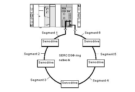
The different segments of the SERCOS® network ::
The diagram below shows the different segments of a SERCOS® network with 5 servodrives connected to it.
Adjustment of optical power of transmitter depending on the length of the segment
Each element of the SERCOS® network (TSX CSY 84 module and servodrives) has an optical transmitter.
For each optical transmitter, the operator must adjust the optical power according to the segment length.
|
Segment length (in meters)
|
Optical power (as a percentage of total power)
|
|
0 < L < 15
|
66%
|
|
15 < L < 40
|
100%
|
-
Optical power of other segments (drive / drive and last drive / module) : it is always provided by the drive's optical transmitter.
Optical power is adjusted via UniLink software by setting parameters for segment length only.

