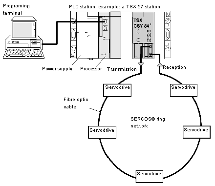
Architecture of a SERCOS® multi-axis control system
The architecture of a SERCOS® multi-axis control system on Premium PLCs includes:
The diagram below gives an example of the architecture of a SERCOS® multi-axis control system.
The multi-axis control system consists of the TSX CSY 84 or TSX CSY 164 multi-axis control modules and the servodrives, interconnected in a network via fiber optic cables.
The drives, which are interconnected through the fiber optic network, act as individual axes.
The motion commands sent by the TSX CSY 84 or TSX CSY 164 modules are sent to each drive in the network and in return, the module receives the actual position values for each axis from the network.
Maximum number of real axes managed by a TSX CSY 84 module
A TSX CSY 84 module manages a maximum of 8 real axes associated with servodrives.
In addition to these real axes, the module can manage:
Number of Application-Specific Modules for a TSX CSY 164 Module
-
Channels 1 to 16 can each support either a real axis function, an imaginary axis function, or an external setpoint:
-
4 groups of coordinated axes (channels 17 to 20).
-
4 groups of slave axes (channels 21 to 24).
-
7 cam profiles (channels 25 to 31).
Project development can be implemented on a terminal (PC) with Control Expert software, allowing:
