|
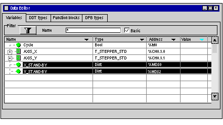
Symbolization of variables in the example
|
|
|
(Original Document)
|

|
Address
|
Symbol
|
Comment
|
|---|---|---|
|
%M0
|
CYCLE
|
Condition of the machine in work mode
|
|
%MD50
|
X_STAND-BY
|
Stand-by position (X axis)
|
|
%MD52
|
Y_STAND-BY
|
Stand-by position (Y axis)
|
|
%MD54
|
X_B
|
Position of belt B (X axis)
|
|
%MD56
|
Y_B
|
Position of belt B (Y axis)
|
|
%MD58
|
X_C
|
Position of belt C (X axis)
|
|
%MD60
|
Y_C
|
Position of belt C (Y axis)
|
|
Address
|
Symbol
|
Comment
|
|---|---|---|
|
%I0.3.0
|
SENSOR_1
|
Detector to detect presence of machined part
|
|
%I0.3.1
|
SENSOR_2
|
Sensor to identify the part type (0 = type 2, 1 = type 1)
|
|
%I0.3.2
|
SENSOR_3
|
Sensor to detect claw open / claw closed
|
|
%I0.3.3
|
AUTO_MAN
|
Switch to select mode (0 = Auto, 1 = Manual)
|
|
%I0.3.4
|
START_CYCLE
|
Push button to execute automatic cycle
|
|
%I0.3.5
|
STOP_CYCLE
|
Push button to stop automatic cycle
|
|
I%I0.3.6
|
SELECTION_X_Y
|
Select axis to drive in Manual mode (1 = X, 0 = Y)
|
|
%I0.3.7
|
PO_MAN
|
Manual reference point
|
|
%I0.3.8
|
Forward
|
Move the moving part in the positive direction
|
|
%I0.3.9
|
BACK
|
Move the moving part in the negative direction
|
|
%I0.3.10
|
ACK_ERROR
|
Fault acknowledgment
|
|
%I0.3.12
|
EMERGENCY_STOP
|
Emergency stop
|
|
%I0.3.13
|
OPEN_CLAW
|
Push button to open claw
|
|
%I0.3.14
|
CLOSE_CLAW
|
Push button to close claw
|
|
Address
|
Symbol
|
Comment
|
|---|---|---|
|
%Q0.40.0
|
CLAW
|
Command to open or close the claw (0 = Open, 1 = Close)
|
|
%Q0.4.1
|
Error
|
Signals an error
|
|
Address
|
Symbol
|
Value
|
Comment
|
|---|---|---|---|
|
%KD0
|
SPEED_O_C
|
5000
|
Speed from the reference point along the axis of the X and Y axes
|
|
%KD4
|
SPEED_X_WAIT
|
10000
|
Speed towards the X axis stand-by position
|
|
%KD6
|
SPEED_Y_WAIT
|
10000
|
Speed towards the Y axis stand-by position
|
|
%KD8
|
SPEED_POS_A_X
|
15000
|
Speed towards the X axis belt A position
|
|
%KD10
|
SPEED_POS_A_Y
|
15000
|
Speed towards the Y axis belt A position
|
|
%KD12
|
SPEED_POS_B_X
|
15000
|
Speed towards the X axis belt B position
|
|
%KD14
|
SPEED_POS_B_Y
|
15000
|
Speed towards the Y axis belt B position
|
|
%KD16
|
SPEED_POS_C_X
|
12000
|
Speed towards the X axis belt C position
|
|
%KD18
|
SPEED_POS_C_Y
|
12000
|
Speed towards the Y axis belt C position
|
|
Address
|
Symbol
|
Address
|
Symbol
|
|---|---|---|---|
|
%CH1.3.0
|
AXIS_X
|
%CH1.3.1
|
AXIS_Y
|
|
%I1.3.0.9
|
AT_POINT
|
%I103.1.9
|
AT_POINT_Y
|
|
Address
|
Standard symbol
|
|---|---|
|
%Ir.m.c.0
|
NEXT
|
|
%Ir.m.c.1
|
DONE
|
|
%Ir.m.c.2
|
AX_FLT
|
|
%Ir.m.c.3
|
AX_OK
|
|
%Ir.m.c.4
|
HD_ERR
|
|
%Ir.m.c.5
|
AX_ERR
|
|
%Ir.m.c.6
|
CMD_NOK
|
|
%Ir.m.c.11
|
CONF_OK
|
|
%Ir.m.c.12
|
REF_OK
|
|
%Ir.m.c.16
|
IN_DROFF
|
|
%Ir.m.c.17
|
IN_DIRDR
|
|
%Ir.m.c.18
|
IN_MANU
|
|
%Ir.m.c.19
|
IN_AUTO
|
|
%Ir.m.c.35
|
ST_DRIVE
|
|
%Qr.m.c.0
|
DIRDRV
|
|
%Qr.m.c.1
|
JOG_P
|
|
%Qr.m.c.2
|
JOG_M
|
|
%Qr.m.c.3
|
INC_P
|
|
%Qr.m.c.4
|
INC_M
|
|
%Qr.m.c.5
|
SET_RP
|
|
%Qr.m.c.6
|
RP_HERE
|
|
%Qr.m.c.9
|
ACK_FLT
|
|
%Qr.m.c.10
|
ENABLE
|
|
%Qr.m.c.11
|
EXT_EVT
|
|
%MDr.m.c.22
|
RP_POS
|