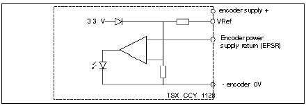
The EPSR input signal from the encoder is comparable to:
-
either a fixed internally generated voltage of 3.3V if the Vref input is not connected.
-
or a voltage equal to 66% of the voltage recorded at the Vref input, positive polarity of the encoder supply voltage.
Diagram of the encoder return supply monitor
The diagram below is of the encoder supply feedback monitor.
The table below summarizes the use of the Vref input according to the encoder supply voltage.
|
If
|
Then
|
|
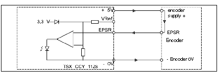
The encoder is using a 5V supply
|
The Vref input is not connected to the positive encoder supply.
The EPSR signal is comparable to the internal voltage of 3.3V. OK if > 3.3V
|
|
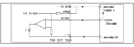
The encoder is using a 10…30V supply
|
The Vref input is connected to the positive encoder supply.
The ESPR signal is comparable to 66% of the encoder supply voltage. OK if >66%
|
Diagram showing the connection process for an encoder on a 10…30V supply
The diagram below shows the connection process for the encoder supply feedback monitor if the encoder is using a 10…30 V supply.
Diagram showing the connection process for an encoder on a 5V supply
The diagram below gives the process for connecting the encoder supply feedback monitor if the encoder is using a 5V supply.
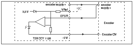
Diagram of the connection process if the encoder has no supply feedback
In this case, the EPSR input is connected to the positive supply at the encoder.