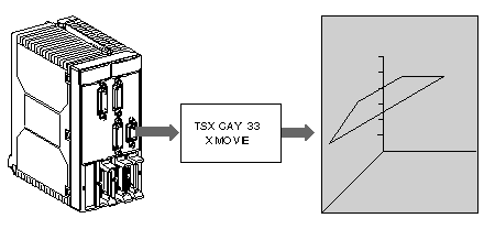
The interpolating function is available with a TSX CAY 33 module, which is used to carry out linear interpolation between 2 or 3 axes.
This module consists of 3 physical channels associated with X, Y and Z axes, and a logic channel (channel 3) dedicated to interpolation.
Before implementing an application for interpolated axes, each of the axes must be set independently. Interpolation can then be carried out between 2 axes (0 and 1) on the (X, Y) plane or between 3 axes (0, 1 and 2) in the (X, Y, Z) space.
For interpolating 2 axes, the third axis (axis 2) can be used and an independent axis.
TSX CAY 33 module does not offer circular interpolation. However, to get from point A to point B following a circular trajectory, it is possible to approximate this type of trajectory by using a succession of straight segments.
Configuring Interpolation
The number of interpolated axes may be set in the interpolator configuration (channel 3), after channels 0 to 2 have been configured as independent axes.
If 2-D is specified, interpolation is implicitly declared on the XY plane ( with X: 0 axis and Y: 1 axis). Channel 2 may be used as an independent axis.
If 3-D is specified, interpolation is implicitly declared in the XYZ space and/or on the planes which make up XY, YZ or XZ space (where X: 0 axis, Y : 1 axis and Z: 2 axis).
Configuring the 2 or 3 independent axes that you would like to interpolate is necessary in order to access interpolator configuration.
Interpolator Channel Programming
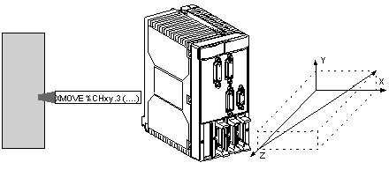
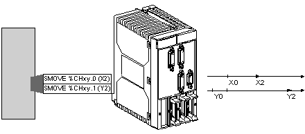
The XMOVE command is used to program interpolated movements. This command is an addition to SMOVE axes, not a substitute.
Axes are only interpolated during the execution of an XMOVE command. Outside of XMOVE commands, they can be commanded independently by an SMOVE command.
Interpolated axes movement command
Independent axes movement command
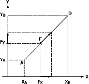
The speed which you specify in the XMOVE command is the desired speed in the direction of movement. The movement speed of each axis is calculated by means of a projection.
Example for a 2 axis system
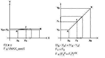
The moving part must move from point A (XA, YA) to point B (XB, YB) at speed F, which projects onto X and Y respectively in FX and FY.
Using value F, which is provided in the XMOVE instruction, the interpolator calculates projections according to the formulae:
Speed F is limited to a maximum speed which depends on:
-
the maximum speeds of each axis affected by the movement,
-
the contribution of each axis within the movement.
Example:
For each XMOVE movement, the duration of the acceleration phase depends on:
-
the speed variations to be performed,
-
the Tacc parameters for the axes affected by the movement,
-
the contribution of X, Y and Z axes.
The resulting calculated acceleration is the fastest that the movement can happen, while respecting the constraints of the different axes (the most constraining axis determines the duration of the acceleration).
The acceleration rule is defined by the SLOPE parameter from channel 3. This imposes a common rule over all axes during an XMOVE independently of SLOPE parameter value for X, Y and Z axes.
