|


|
(Original Document)
|
|
|
(Original Document)
|
|
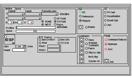
Display zone
|
Description
|
|---|---|
|
X Current
|
Displays the moving part position using the measurement unit defined in the configuration.
|
|
X Target
|
Displays the moving part setpoint position: target position (defined in instruction) (1)
|
|
X Following error
|
Displays the deviation between the setpoint position calculated and the actual position of the moving part (following error).
|
|
F Current
|
Displays the moving part speed using the measurement unit defined in the configuration.
|
|
F Target
|
Displays the setpoint speed of the moving part: target speed (speed defined by CMV coefficient in modulated instruction) (2)
|
|
N / G9x / G
|
These fields display the instruction which is being executed.
N = step number, G9x = movement type, G = instruction code
|
|
Position
|
The bar chart shows the progress of the moving part within the limits defined in the configuration. The bar chart is colored green, and becomes red if the limits are exceeded
|
|
Speed
|
The bar chart expresses the speed of the moving part in relation to maximum speed as a percentage. The bar chart is colored green, and becomes red if the maximum speed is exceeded
|
|
Indicator
|
State
|
Indication
|
|---|---|---|
|
+ Direction
- Direction
|
/
|
Indicates that the part is moving in a positive direction
Indicates that the part is moving in a negative direction
|
|
DONE
|
Lit
|
Indicates that the movement(s) in progress are now finished
|
|
NEXT
|
Lit
|
Indicates that the module is ready to receive a movement command
|
|
AT Point
|
Lit
|
Indicates that the movement in progress has finished, and that the moving part is in the target window (for instructions with stop)
|
|
TH Point
|
Lit
|
Indicates that the theoretical setpoint has been reached
|
|
Feed hold
|
Lit
|
Indicates that the Feed hold function has been activated (the CMV coefficient is set at 0)
|
|
LED / Button
|
State
|
Indication
|
|---|---|---|
|
OK
|
Lit
|
Axis in operational state (no blocking fault)
|
|
Referenced
|
Lit
|
Referenced axis
|
|
Stopped
|
Lit
|
Moving part stationary
|
|
Enable
|
/
|
This button is used to control the variable speed controller enable relay
|
|
LED
|
Indication
|
|---|---|
|
PO Cam
|
Signal state (0 or 1) on Reference point input
|
|
Recalibration
|
Signal state (0 or 1) on Recalibration input
|
|
Event Cam
|
Signal state (0 or 1) on Event input
|
|
Aux
|
Signal state (0 or 1) on auxiliary output
|
|
Command
|
Description
|
|---|---|
|
STOP
|
Stops the moving part according to deceleration defined in the configuration
|
|
Param
|
Used to enter external values (position tracking function)
|
|
CMV
|
Used to enter a value from 0 to 2000 which determines the speed multiplier coefficient (0.000 to 2000 in intervals of 1/1000)
|
|
Indicator
|
State
|
Indication
|
|---|---|---|
|
PRef
|
Lit
|
Indicates PREF position latching (1)
|
|
PRef1
|
/
|
This field displays the memorized PREF1 position (1)
|
|
PRef2
|
/
|
This field displays the memorized PREF2 position (1)
|
|
End G10/G11
|
Lit
|
Indicates event arrival while G10 or G11 instruction is being executed
|
|
End G05
|
Lit
|
Indicates that execution of instruction G05 is complete
|
|
TO G05
|
Lit
|
Indicates that the Time Out, defined in instruction G05, has elapsed
|
|
Command
|
Description
|
|---|---|
|
Slave
|
Changes the axis to slave mode (slave of another axis). 0 axis cannot be set to slave axis mode
|
|
External Command
|
Changes the axis to a slave of periodic setpoint
|
|
Pause
|
Commands the moving part to stop at the end of a movement with a stop in progress
|
|
Step by step
|
Changes the axis to Step by step mode
|
|
Next step
|
In Step by step mode, activates the waiting movement
|
|
Synchro UC
|
Triggers a PLC event
|
|
LED / Button
|
State
|
Indication
|
|---|---|---|
|
Command Refused
|
Lit
|
Last command refused
|
|
Hardware
|
Lit
|
External hardware fault (e.g. encoder, variable speed controller, outputs, etc.)
|
|
Axis
|
Lit
|
Application fault (e.g. following error, software limits, etc.)
|
|
Ack.
|
/
|
Fault acknowledgment button. Activating this button acknowledges all faults which have disappeared
|
