The following parameters are used to adjust the position loop:
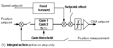
The following synoptic shows the position control loop:
Position and speed references are created according to the movement which is required (e.g. speed, target position), and the parameters which have been defined in the Adjustment screen.
Description of Gain Parameters
This table describes the gain parameters:
|
Parameter
|
Meaning
|
|
Gain 1 and Gain 2
|
Position loop gains (from 50 to 12,000 1/100 s).
By default: Gain 1 = Gain 2 = 1000 1/100 s
The axis control module uses the 2 gain values:
-
Gain 1: gain value for high operating speeds. This value is used to avoid overshoot and instability.
-
Gain 2: gain value for low operating speeds. This value is used to obtain very slight position deviations.
|
|
Threshold of 1 to 2
|
Gain switching threshold (from 20 to 500% of VMAX)
By default: Gain threshold = 500% of VMAX
|
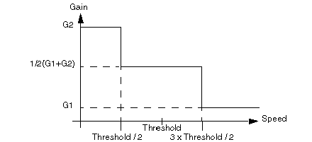
The applied position gain is as follows:
-
If the current speed > = 3 x Threshold / 2, Gain = Gain 1
-
If 3 x Threshold / 2 > current speed> = Threshold / 2, Gain = (Gain 1 + Gain 2) / 2
-
If current speed < Threshold / 2, Gain = Gain 2
This drawing shows gain value according to current speed:
Proportional Gain Coefficient
The axis control module calculates the KP proportional gain coefficient on the basis of the Gain adjustment: KP = C x UMAX x Gain
C = constant, and UMAX = variable speed controller setpoint value in order to obtain the speed VMAX (UMAX < 9 V).
NOTE: In general, Gain 1 = Gain 2.
Description of Feed Forward Parameter
This table shows the feed forward parameter:
|
Parameter
|
Meaning
|
|
Feed forward
|
Feed forward adjustment coefficient (from 0 to 100%).
By default: Feed forward = 10%
|
The feed forward coefficient is expressed as a percentage. 100% corresponds to the value, which can completely absorb the position error at constant speed for a variable speed controller without continuous error.
When the feed forward coefficient rises, the position error is reduced. However this results in a risk of overrun, including when approaching the breakpoint. A compromise must therefore be found.
NOTE: In certain cases, the position error crosses a minimum threshold with a change of sign if the feed forward rises.
Description of Offset Parameter
This table describes the offset parameter:
|
Parameter
|
Meaning
|
|
Offset
|
Offset adds to the analog output value calculated by the loop (from –250 mV to +250 mV).
By default: Offset = 0 mV
|


