|
TSX CAY Module Configuration
|
|
|
(Original Document)
|
|
Step
|
Action
|
|---|---|
|
1
|
Open the Station file (either by double clicking on the icon or clicking on its link).
|
|
2
|
Open the Configuration file (either by double clicking on the icon or clicking on its link).
|
|
2
|
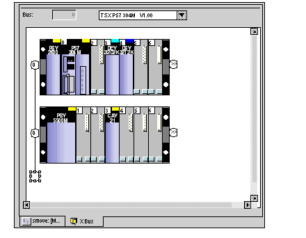
Open the Bus X file (either by double clicking on the icon or clicking on its link).
|

|
Step
|
Action
|
|---|---|
|
1
|
Select position 3 of Rack 1, then execute the Edit → Open module command (or double click on the selected module).
|
|
2
|
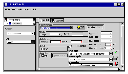
Configure the parameters of channel 0. To do this:
Channel 0 configuration screen
 |
|
3
|
Set the adjustment parameters according to the configuration.
Mandatory fields are in red
|
|
4
|
Confirm your entries with the Edit → Confirm command or by clicking on the icon
 |
|
5
|
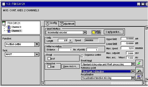
Configure the parameters of channel 1 then validate your entries, by following the same procedure as for channel 0:
Channel 1 configuration screen
 |
|
6
|
Set the adjustment parameters according to the configuration.
Mandatory fields are in red
|
|
7
|
In the main screen of the configuration editor, validate the configuration using the Edit → Confirm command or by clicking on the icon
 |
|
Parameter
|
Designation
|
Value
|
Comment
|
|---|---|---|---|
|
Units
|
Physical length unit
|
mm
|
|
|
Units
|
Physical speed unit
|
mm/min
|
automatically deduced
|
|
Initial resolution
|
Distance
|
4000
|
|
|
Initial resolution
|
No. of points
|
4000
|
|
|
Encoder type
|
Absolute
|
||
|
Encoder type
|
Offset
|
Direct
|
|
|
Encoder type
|
Code
|
Binary
|
|
|
Encoder type
|
No. of header bits
|
0
|
|
|
Encoder type
|
No. of data bits
|
24
|
|
|
Encoder type
|
No. of status bits
|
0
|
|
|
Encoder type
|
Parity
|
Odd
|
|
|
Max. setpoint
|
9000 mV
|
||
|
Speed
|
Maximum speed of the moving part
|
5400
|
|
|
Max. acceleration
|
300 ms
|
||
|
Upper limit
|
Upper axis limit
|
900000
|
|
|
Lower limit
|
Lower axis limit
|
0
|
|
|
Event
|
Rising edge and PREF1
|
||
|
Reference point
|
No reference point
|
|
Parameter
|
Designation
|
Value
|
Comment
|
|---|---|---|---|
|
Units
|
Physical length unit
|
mm
|
|
|
Units
|
Physical speed unit
|
mm/min
|
Automatically deduced
|
|
Initial resolution
|
Distance
|
2000
|
|
|
Initial resolution
|
No. of points
|
500
|
|
|
Encoder type
|
Incremental
|
Default choice
|
|
|
Encoder type
|
x 1
|
Default choice
|
|
|
Encoder type
|
Code
|
Binary
|
|
|
Max. setpoint
|
9000 mV
|
||
|
Speed
|
Maximum speed of the moving part
|
5400
|
|
|
Max. acceleration
|
200 ms
|
||
|
Upper limit
|
Upper axis limit
|
500000
|
|
|
Lower limit
|
Lower axis limit
|
-5000
|
|
|
Event
|
Rising edge and PREF1
|
||
|
Reference point
|
Long cam
Top Z
- Direction
|