Reference Point
(Original Document)
Introduction
An incremental encoder does not measure the position but supplies a number of pulses proportional to a movement.In order for this movement to be transformed into a position, a known value must assigned to a particular point on the axis (usually chosen as 0).This operation is called setting a reference point.An axis which has been given a reference point, is classed as referenced.
Reference Point Field
The Reference point field defines the type and direction of the reference point (only when an incremental encoder has made the position measurement).
The type is defined by using 2 source detection inputs :zero marker input and cam input.
Possibilities
Approach speed (1)
RP Speed
Icon
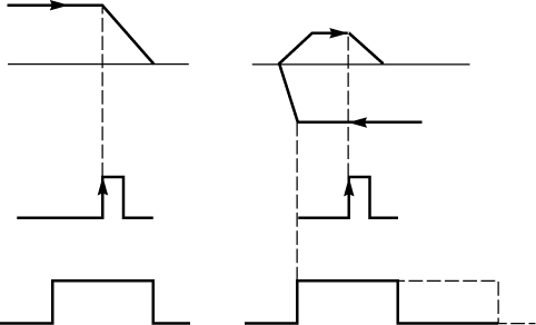
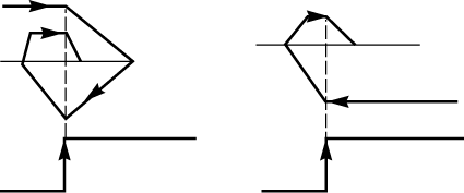
short cam (2) and zero latch, + direction
F
F
(3)
short cam (2) and zero latch, - direction
F
F/8
(3)
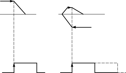
Short cam (2), + direction
F
F
(3)
Short cam (2), - direction
F
F/8
(3)
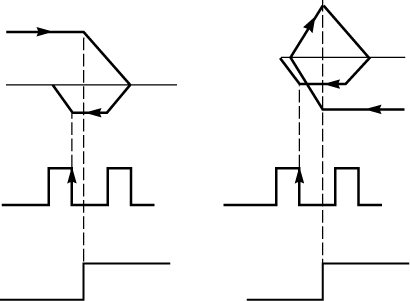
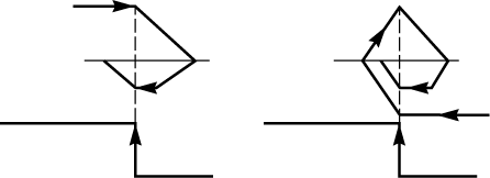
Long cam (2) in stop and zero latch, + direction
F
F/8
(3)
Long cam (2) in stop and zero latch, - direction
F
F/8
(3)
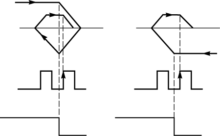
Long cam (2) in stop, + direction
F
F/8
(3)
Long cam (2) in stop, - direction
F
F/8
(3)
(1) F is the speed programmed in the instruction in automatic mode or the speed FMANU (defined in the adjustment screen) in manual mode.This speed can be modulated by the SMC coefficient.
(2) Only short cam reference points can be used when the machine is of infinite type.
(3) The icon illustrates the reference point.
Reference Point Command
The reference point command is given:
Forced Reference Point
There is also a forced reference point mechanism:
This method of setting a reference point forces the position to a specified value.This operation does not entail any movement and does take account of the type of RP selected.
Reference Point Short Cam
The following table provides a detailed description of short cam reference points :
Type
Short cam / zero latch
Short cam only
Direction
+ Direction
- Direction (1)
+ Direction
- Direction (1)
Icon
Movement Zero latch Cam
(1) or start on cam
Reference Point Long Cam
The following table provides a detailed description of the long cam and zero latch reference points:
Type
Long cam in stop / zero latch
Direction
+ Direction (2)
- Direction (2)
Start
Start off cam
Start on cam
Start on cam
Start off cam
Icon
Movement Zero latch Cam
The following table provides a detailed description of long cam only reference points:
Type
Long cam in stop
Direction
+ Direction (2)
- Direction (2)
Start
Start off cam
Start on cam
Start on cam
Start off cam
Icon
Cam Movement
(2) defines the place on the machine where the cam is situated.
TSX CAY •2 and TSX CAY 33: Zero Latch Presence Monitoring
Reference point short cam monitors the presence of the zero latch along the length of the cam.
During a short cam type of reference point setting, in + direction or – direction, with zero latch, if all the cam is covered without detecting any zero latches, the axis stops at the output of the cam and an error is signaled.The axis goes into a non-referenced state.