|
External Operating Voltage Connections
|
|


|
Original instructions
|
|
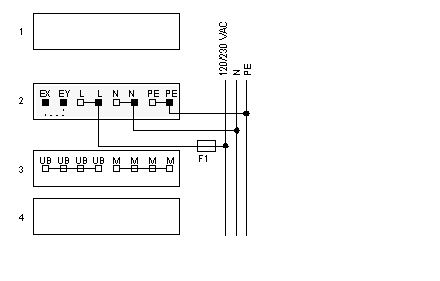
External Operating Voltage Connections
|
|
|
Original instructions
|
|
Row
|
Terminal
|
Connection
|
Function
|
|---|---|---|---|
|
2
|
1
|
EX
|
Jumper connection
|
|
2
|
2
|
EY
|
Jumper connection
|
|
2
|
3, 4
|
L
|
AC input voltage, line
|
|
2
|
5, 6
|
N
|
AC input voltage, neutral
|
|
2
|
7, 8
|
PE
|
Earth ground
|
|
3
|
1, 2, 3, 4
|
UB
|
DC output voltage
|
|
3
|
5, 6, 7, 8
|
M
|
DC output voltage return
|
|
Voltage
|
Jumper Placement
|
External Fusing (min. F1)
|
|---|---|---|
|
120 VAC
|
Mounted
|
0.63 A slow-blow
|
|
230 VAC
|
Removed
|
0.315 A slow-blow
|
