Analog Channel Parameters
Original instructions
Overview
Parameters must be set for all of the analog channels before the module can be commissioned. This section provides the codes for setting the parameters and gives examples of parameter settings.
NOTE: If you set new parameters for the module, always send a complete set of parameters (all channels, inputs and outputs), even if you only want to change a single parameter. Otherwise the module will refuse the new parameters and continue working with the old ones.
Key
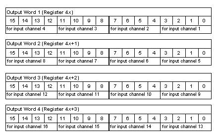
This section focuses on output words 1 ... 4, as highlighted in the table below:
Word
Input Data
Output Data
1 = LSW
Value, input channel 1
Parameters for input channels 1 ... 4
2
Value, input channel 2
Parameters for input channels 5 ... 8
3
Value, input channel 3
Parameters for input channels 9 ... 12
4
Value, input channel 4
Parameters for input channels 13 ... 16
5 ... 15
Value, input channel 5 ... 15
Not used
16 = MSW
Value, input channel 16
Not used
Illustration
Parameters are set by entering a four-bit code in output words 1 ... 4, as follows:
Codes for Analog Input Parameters
Use the following codes to set the parameters for each analog input channel:
Code (binary)
Code (hex)
Parameter
0000
0
Reserved value (see note below)
1010
A
+/-5V input range
1011
B
+/-10V input range
1100
C
Channel inactive
1110
E
4 ... 20 mA
NOTE: The 0000 reserved value is more a control than a parameter. It forces the I/O base into a default condition where it continues to receive field inputs according to the previous channel parameters.