|
I/O Mapping
|
|
|
Original instructions
|
|
Word
|
Input Data
|
Output Data
|
|---|---|---|
|
1
|
Status word (module status)
|
System information
|
|
2
|
State of the 8 discrete inputs
|
Register for discrete reaction in a fail state
|
|
3
|
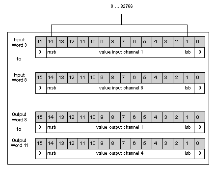
Analog input word channel 1
|
Register for analog reaction in a fail state
|
|
4
|
Analog input word channel 2
|
User defined analog fail state values for channel 1
|
|
5
|
Analog input word channel 3
|
User defined analog fail state values for channel 2
|
|
6
|
Analog input word channel 4
|
User defined analog fail state values for channel 3
|
|
7
|
Analog input word channel 5
|
User defined analog fail state values for channel 4
|
|
8
|
Analog input word channel 6
|
State of the 8 discrete outputs
|
|
9
|
Not used
|
Analog output word channel 1
|
|
10
|
Not used
|
Analog output word channel 2
|
|
11
|
Not used
|
Analog output word channel 3
|
|
12
|
Not used
|
Analog output word channel 4
|

