|
Field Wiring Guidelines
|
|
|
Original instructions
|
|
Type
|
Part Number
|
|---|---|
|
Screw-in
|
170 XTS 001 00
|
|
Spring-clip
|
170 XTS 002 00
|
|
Type
|
Part Number
|
|---|---|
|
Screw-in
|
170 XTS 006 01
|
|
Spring-clip
|
170 XTS 007 01
|
 CAUTION CAUTION |
|
VOLTAGE SPIKE MAY BE SUFFICIENT TO DAMAGE OR DESTROY MODULE
If an external switch is wired to control an inductive load in parallel with the module output, then an external varistor (Harris V390ZA05 or equivalent) must be wired in parallel with the switch.
Failure to follow these instructions can result in injury or equipment damage.
|
|
Row
|
Terminal
|
Connection
|
|
|---|---|---|---|
|
2
|
1
|
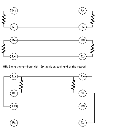
RxHi
|
Modbus Master RS485
|
|
2
|
RxLo
|
Modbus Master RS485
|
|
|
3
|
TxHi
|
Modbus Master RS485
|
|
|
4
|
TxLo
|
Modbus Master RS485
|
|
|
5
|
PE
|
Earth Ground
|
|
|
6
|
-
|
Not Used
|
|
|
7 ... 12
|
I1 ... I6
|
Inputs 1 ... 6
|
|
|
13 ... 16
|
2N
|
Voltage for input field devices, Neutral
|
|
|
17
|
N
|
Module operating voltage, Neutral
|
|
|
18
|
L1
|
Module operating voltage, Line
|
|
|
3
|
1 ... 4
|
PE
|
Earth Ground
|
|
5
|
-
|
Not Used
|
|
|
6, 8, 10
|
O1 ... O3
|
Outputs 1 ... 3
|
|
|
7, 9, 11 ... 16
|
1N
|
Voltage for output field devices, Neutral
|
|
|
17
|
1N
|
Voltage for output field devices, Neutral
|
|
|
18
|
1L1
|
Voltage for field devices, Line
|
|
|
4
|
18
|
PE
|
Earth Ground
|
