|
Register for Outputs
|
|


|
Original instructions
|
|
Register for Outputs
|
|
|
Original instructions
|
|
Word
|
Function
|
|---|---|
|
1
|
System information
|
|
2
|
Register for discrete reaction in a fail state
|
|
3
|
Register for analog reaction in a fail state
|
|
4
|
User defined analog fail state values for channel 1
|
|
5
|
User defined analog fail state values for channel 2
|
|
6
|
State of the 8 discrete outputs
|
|
7
|
Analog output word channel 1
|
|
8
|
Analog output word channel 2
|
 CAUTION CAUTION |
|
Zero is an illegal value for the parameter field (words 1-5).
A zero value in the parameter field will cause an output shut down state, and no inputs or outputs are updated. Any bit set in the parameter field, including those defined as not used, will enable the module.
Failure to follow these instructions can result in injury or equipment damage.
|
|
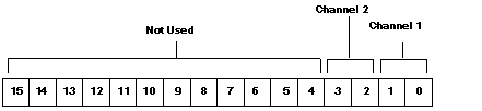
Word 1
|
Description
|
|---|---|
|
Bits 0 ... 14
|
Not used
|
|
Bit 15
|
0 = Disables user defined shutdown values.
1 = Enables user defined shutdown values.
|
|
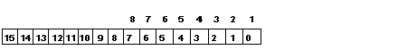
Word 2
|
Description
|
|---|---|
|
Bit 0 ... 7
|
Discrete fail state value for outputs 1 ... 8
|
|
Bits 8 ... 13
|
Not used
|
|
Bit 14
|
0 = hold last value, 1 = user defined value
|
|
Bit 15
|
0 = all outputs reset, 1 = check bit 14
|
|
2 Bit Value
|
Fail State
|
|---|---|
|
00
|
Minimum output voltage
|
|
01
|
Hold last value (default)
|
|
10
|
User defined shutdown value
|
|
11
|
Hold last value (not normally used)
|