Surge Protection for Bus Leads up to 12 Mbps Signals
To protect transmission systems from extraneous surges (lightning), the PROFIBUS DP lead should be equipped with suitable surge protection equipment once it extends outside a building.
The nominal discharge current should be at least 5 kA.
Examples of compatible lightning arrestors include
Type CT MD/HF5 and
Type CT B110 made by the firm Dehn und Söhne GmbH & Co KG. For supplier addresses and order numbers, see
Ordering Details for PROFIBUS DP Components.
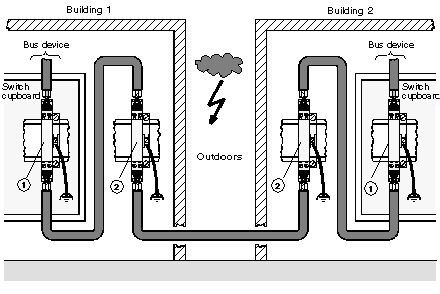
For adequate protection of a PROFIBUS DP cable, two sets of protection equipment are required for each building. The first set of protection devices (type B110), located where the cable enters the building, works as a lightning conductor, the second (type MD/HF5), located near the first device, works as a surge protection device.
Connection Rules for Protection Equipment
Before connecting the protection equipment, please pay close attention to the following rules:
-
Install a functional ground (potential-equalization rod)
-
Install the protection equipment near the functional ground, to keep surge current path as short as possible.
Keep the lead to the functional earth as short as possible. (minimum 6mm2)
-
The maximum lead length depends on the transfer rate.
-
Up to 500 kbps you may configure a maximum of 4 outdoor sections with 8 pairs of protection devices (CT B110 and CT MD/HF5).
-
From 1MBaud up to the highest transfer rate you may only configure 1 outdoor section with 2 pairs of protection devices.
-
Do not mix up the IN and OUT sides of the lightning conductors (IN = outdoor side)
-
Carry out a
shield grounding of the PROFIBUS DP lead according to the type of lightning conductor (type CT B110 or CT MD/HF5) being used.
Connection Plan for Protection Devices
Connection plan of the protection devices:
Type and number of lightning conductors made by the firm Dehn und Söhne GmbH &Co KG suitable for a PROFIBUS DP cable
|
No.
|
Type
|
Number per Group
|
|
1
|
CT MD/HF 5
|
2
|
|
2
|
CT B110
|
2
|
NOTE: Information about mounting and connecting the leads can be found in the relevant installation instructions, which are enclosed with the lightning conductors.
Shield Grounding of Surge Protection Devices
The protection devices permit direct or indirect shield grounding. The gas-type surge protector acts as an indirect ground.
In both cases EMC spring terminals grasp the input and output sides of the cable shield.
NOTE: When the system permits it, we recommend you use direct shield grounding.
Types of shield grounding assignment
|
Type of grounding
|
Assignment
|
|
Direct shield grounding
|
Connect the shield of the incoming cable to the IN terminal, and that of the outgoing cable to the OUT terminal. The shields are now galvanically connected to the PE.
|
|
Indirect shield grounding via gas-type surge protector
|
Connect shields as described for direct shield grounding. Insert the gas-type surge protector in the rack beneath the cabinet connection terminals on the input side.
|
NOTE: Information about grounding and shield grounding can be found in the relevant installation instructions which are enclosed with the lightning conductors.
