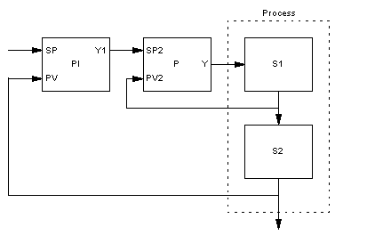
Structure diagram of the PIP cascade controller
Setting parameters for the function block takes place firstly through the pure PI – parameter, that is to say the proportional correction value gainl and the reset time ti.
The I component can be disabled by setting ti = 0.
Subsequently setting parameters for the P controller takes place through the proportional correction value gain2.
Manipulated variable limiting
Manipulated variable limiting takes place at the output of the sub controller, which means:
ymin ≤ Y ≤ ymax
Anti-windup reset (PI controller)
If manipulated variable limiting takes place, the anti-windup reset should make sure that the integral component of the master controller "is not able to exceed all limits". The anti-windup measure can only be used if the I-component of the controller is not disabled (ti = 0).
The anti-windup limits for the PI master controller are adjusted dynamically to the present system deviation of the sub controller and the ymax and ymin limits.
If manipulated variable limiting takes place, the integral component will be limited as follows:


