|
Description
|
|
|
Original instructions
|
 WARNING WARNING |
|
UNEXPECTED OUTPUT BEHAVIOUR
Make sure that the function block is always invoked in the first program cycle.
Failure to follow these instructions can result in death, serious injury, or equipment damage.
|
|
Controller
|
Transfer function
|
|---|---|
|
Master controller (PI-controller)
|
 |
|
Sub controller (P controller)
|
 |


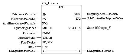
CAL PIP_Instance (SP:=ReferenceVariable,
    PV:=ControlledVariable, PV2:=AuxiliaryControlVariable,
    MODE:=OperatingModes, PARA:=Parameter,
    YMAN:=ManualValue, SP_FIX:=FixedValue, OFF:=Offset,
    Y:=ManipulatedVariable, ERR=>OutputSystemDeviation,
    SP2=>SubControllerSetpointValue,
    STATUS=>StatusOfOutput_Y)
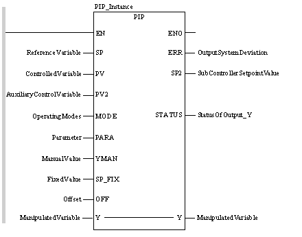
PIP_Instance (SP:=ReferenceVariable,
    PV:=ControlledVariable, PV2:=AuxiliaryControlVariable,
    MODE:=OperatingModes, PARA:=Parameter,
    YMAN:=ManualValue, SP_FIX:=FixedValue, OFF:=Offset,
    Y:=ManipulatedVariable, ERR=>OutputSystemDeviation,
    SP2=>SubControllerSetpointValue,
    STATUS=>StatusOfOutput_Y) ;
|
Parameter
|
Data type
|
Description
|
|---|---|---|
|
SP
|
Reference variable
|
|
|
PV
|
REAL
|
Controlled variable for the master controller
|
|
PV2
|
REAL
|
Controlled variable for the sub controller (auxiliary control variable)
|
|
MODE
|
Operating mode
|
|
|
PARA
|
Parameter
|
|
|
YMAN
|
REAL
|
Manual value (of output Y)
|
|
SP_FIX
|
REAL
|
Fixed value (reference variable as manual value for the sub controller)
|
|
OFF
|
REAL
|
Offset at the output of the P-controller
|
|
Parameter
|
Data type
|
Description
|
|---|---|---|
|
Y
|
REAL
|
Manipulated variable
|
|
Parameter
|
Data type
|
Description
|
|---|---|---|
|
ERR
|
REAL
|
System deviation
|
|
SP2
|
REAL
|
Sub controller setpoint value
|
|
STATUS
|
Y output status
|
|
Element
|
Data type
|
Description
|
|---|---|---|
|
man
|
"1": Manual mode
|
|
|
halt
|
BOOL
|
"1": Halt mode
|
|
fix
|
BOOL
|
"1": Fixed setpoint control
|
|
Element
|
Data type
|
Description
|
|---|---|---|
|
gain1
|
Proportional action coefficient (gain) for PI controller
|
|
|
ti
|
PI controller reset time
|
|
|
gain2
|
REAL
|
Proportional action coefficient (gain) for P controller
|
|
ymax
|
REAL
|
Upper limit
|
|
ymin
|
REAL
|
Lower limit
|
|
Element
|
Data type
|
Description
|
|---|---|---|
|
qmax
|
"1" = Y has reached the upper control limit
|
|
|
qmin
|
BOOL
|
"1" = Y has reached the lower control limit
|
