|
Description
|
|
|
Original instructions
|
 WARNING WARNING |
|
UNEXPECTED OUTPUT BEHAVIOUR
Make sure that the function block is always invoked in the first program cycle.
Failure to follow these instructions can result in death, serious injury, or equipment damage.
|

|
Variable
|
Description
|
|---|---|
|
YD
|
D component
|
|
YI
|
I component
|
|
YP
|
P component
|


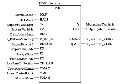
CAL PIDP1_Instance (MAN:=ManualMode, HALT:=HaltMode,
    SP:=SetpointValueInput, PV:=ProcessVariable,
    BIAS:=DisturbanceInput, D_ON_X:=D_PortionValueFlag,
    REVERS:=OutputReversed, KP:=ProportionalRate,
    KI:=IntegralRate, KD:=DifferentiationRate,
    TD_LAG:=LagTimeD_Portion, YMAX:=UpperControlLimit,
    YMIN:=LowerControlLimit, YMAN:=ManualValue,
    Y=>ManipulatedVariable, ERR=>OutputSystemDeviation,
    QMAX=>Y_Reached_YMAX, YMIN=>Y_Reached_YMIN)
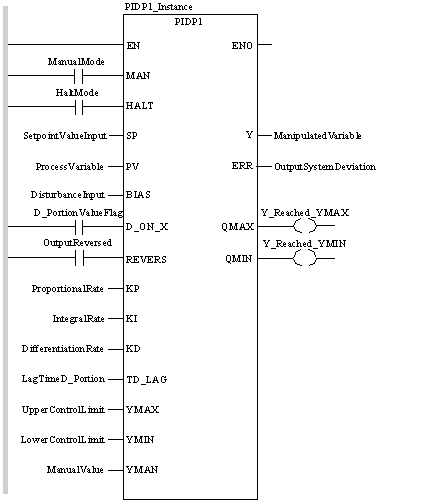
PIDP1_Instance (MAN:=ManualMode, HALT:=HaltMode,
    SP:=SetpointValueInput, PV:=ProcessVariable,
    BIAS:=DisturbanceInput, D_ON_X:=D_PortionValueFlag,
    REVERS:=OutputReversed, KP:=ProportionalRate,
    KI:=IntegralRate, KD:=DifferentiationRate,
    TD_LAG:=LagTimeD_Portion, YMAX:=UpperControlLimit,
    YMIN:=LowerControlLimit, YMAN:=ManualValue,
    Y=>ManipulatedVariable, ERR=>OutputSystemDeviation,
    QMAX=>Y_Reached_YMAX, YMIN=>Y_Reached_YMIN) ;
|
Parameter
|
Data type
|
Description
|
|---|---|---|
|
MAN
|
"1": Manual mode
|
|
|
HALT
|
BOOL
|
"1": Halt mode
|
|
SP1
|
Setpoint input
|
|
|
PV1
|
REAL
|
Input variable
|
|
BIAS
|
REAL
|
Disturbance input
|
|
D_ON_X
|
BOOL
|
1: D component in relation to the controlled variable
0: D component in relation to the system deviation
|
|
REVERSE
|
BOOL
|
1: Output reversed
|
|
KP
|
REAL
|
Proportional action coefficient (gain)
|
|
KI1
|
REAL
|
Integral action coefficient
|
|
KD
|
REAL
|
Derivative time constant
|
|
TD_LAG
|
Delay, D component
|
|
|
YMAX
|
REAL
|
Upper limit
|
|
YMIN
|
REAL
|
Lower limit
|
|
YMAN
|
REAL
|
Manually manipulated value
|
|
Parameter
|
Data type
|
Description
|
|---|---|---|
|
Y
|
REAL
|
Manipulated variable
|
|
ERR
|
REAL
|
System deviation
|
|
QMAX
|
BOOL
|
1 = Y has reached the upper control limit
|
|
QMIN
|
BOOL
|
1 = Y has reached the lower control limit
|
