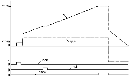
The jump response of the
PI controller is shown in the following
Diagram as an example.
In the first part of the figure the function block response to MAN operating mode can be seen: The output Y jumps to the YMAN value.
The second part of the diagram shows the reaction of the function block in automatic mode (MAN = 0 and HALT= 0) both with a positive ERR system deviation and with a negative ERR system deviation. For constant positive system deviation, Y ramps upward until the upper output limit is reached.
Y is then limited to the value ymax. Limiting is signaled by qmax. The system deviation then jumps to a negative value whose absolute value is greater than the previous positive value.
The input jumps to the value

); through the P component, then there is a ramp decrease in
Y. The absolute value of the gradient is greater than under the previous positive system deviation. This can be attributed to the now greater absolute value of the system deviation.
PI controller jump response
Presentation of the jump response of the PI controller
 ); through the P component, then there is a ramp decrease in Y. The absolute value of the gradient is greater than under the previous positive system deviation. This can be attributed to the now greater absolute value of the system deviation.