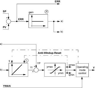
The following is the structure diagram of the PI controller:
The
PI control structure is displayed in the
Structure diagram. Setting parameters for the function block takes place first of all for the elemental
PI parameters: the proportional action coefficient
gain and reset time
ti.
The I component can be disabled by setting ti = 0.
The values ymax and ymin limit the output within the prescribed range. Therefore ymin ≤ Y ≤ ymax.
The outputs qmax and qmin signal that the output has reached a limit, and thus been capped.
-
qmax = 1 if Y ≥ ymax
-
qmin = 1 if Y ≤ ymin
Manipulated variable limiting
After summation of the components manipulated variable limiting takes place, so that: ymin ≤ Y ≤ ymax
Should limiting of the manipulated variable take place, the antiwindup reset should ensure that the integral component "cannot go berserk". The antiwindup measure is only implemented if the I component of the controller is not disabled. Anti-windup limits are identical to those for the manipulated variable. The anti-windup-reset measure corrects the I component such that: ymin - YP ≤ YI ≤ ymax - YP