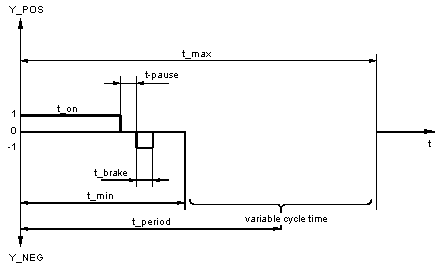
The pulse duration t_on determines the time span in which the output Y_POS resp. Y_NEG has 1 signal. For a positive input signal X the output Y_POS is set, for a negative input signal X the output Y_NEG is set. Only one output can carry 1 signal. It is advisable to perform a freely definable pause time of t_pause = 10 or 20 ms between the actuating and brake pulses to protect the power electronics (hopefully preventing simultaneous firing of the antiparallel connected thyristors).
A possible brake pulse of duration time t_brake follows the output pulse duration after a pause time t_pause. Within the pause time both outputs carry 0 signals. During the braking time the output opposite that carrying the previous pulse goes to 1 signal. A pause time of t_pause = 20 ms (t_pause =0.02) corresponds to an interruption of the firing angle control for two half waves. That should guarantee a sufficiently large safety margin for the prevention of short-circuits resp. triggering of the suppressor circuitry as a consequence of antiparallel thyristors firing.
Thereafter follows a period in which both outputs carry 0 signal (delay).
Period

This delay, together with the pulse, pause and brake times, all makeup a period

, which depending on lo_x and
t_min, is calculated according to the following formulas:
|
Requirements
|
Equation
|
Explanation of formula variables
|
|
lo_x <> 0
|
|
|
|
lo_x = 0
t_min > 0
|
|
|
|
lo_x = 0
t_min = 0
|
|
|
The following holds for all three cases:
|
Requirements
|
lo_x
|
up_x
|
t_min
|
t_max
|
|
|
pos_lo_x
|
pos_up_x
|
pos_t_min
|
pos_t_max
|
|
|
neg_lo_x
|
neg_up_x
|
neg_t_min
|
neg_t_max
|
NOTE: From the parameters up_x (-pos/-neg) and lo_x (-pos/-neg) only the (absolute) value is evaluated.
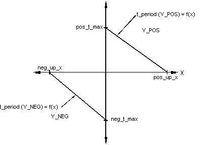
The parameter t_min - for every output there is a separate value - gives the minimum period, i.e. the time span, which passes from the beginning of one actuating pulse until the start of the next. This time span appears when input X goes beyond value up_x - this time there is a separate value for each sign.
The parameter t_max places an upper limit on the maximum period. Should the input cross below the value pos_lo_x or neg_lo_x, the actuating pulse output is terminated until the until the input exceeds the value pos_lo_x or neg_lo_x again. The values pos_lo_x and neg_lo_x define what is in principle a dead zone, in which the function block outputs are not activated.
The parameters (pos_t_min, pos_up_x) and (pos_t_max, pos_lo_x) are valid for positive input signals X. The output Y_POS is set. The parameters Parameter (neg_t_min, neg_up_x) and (neg_t_max, neg_lo_x) are valid for negative input signals X. The output Y_NEG is set.
An overview of the ratio between times is shown in the following diagram:
In the following picture the dependency of the output on X is shown:
Output dependency on
X (Special case)
In the following picture the special case t_min = 0, lo_x = 0 is shown:
In reset mode R = "1", outputs Y_POS and Y_NEG are set to 0 signal. The internal time meters are also standardized, so that the function block begins the transfer to R=0 with the output of a new 1 signal on the associated output.
If the PDM function block is operated together with a PID controller, then the maximum period t_max should be selected so that it corresponds to the PID controller's scan time. It is then guaranteed that every new actuating signal from the PID controller within the period time can be fully processed.
The PDM scan time t_scan should be in proportion with the period vs. pulse time. Though this, the smallest possible actuating pulse is be determined.
The following ratio is recommended:
 , which depending on lo_x and t_min, is calculated according to the following formulas:


