Setting function block parameters is initially performed by the pure PID parameters, i.e. the proportional action coefficient gain, the reset time ti and the derivative time td.
The D component is delayed by the time td_lag. The td/td_lag ratio is termed the differential gain, and is generally selected between 3 and 10. The D component can either be based upon the system deviation ERR (d_on_pv = "0") or the controlled variable PV (d_on_pv = "1"). Should the D component be determined by the controlled variable PV, then the D component will not be able to cause jumps when reference variable fluctuations (changes in input SP) take place. Generally, the D component only affects disturbances and process variances.
NOTE: The EFB has 3 I/O parameters (SP_CAS, OFF, YMAN) that are updated by the function itself in cascade mode. To use the block in cascade mode, you have to establish the connection between these inputs and the appropriate outputs (SP_CAS_N, OFF_N, YMAN_N) through variables.
Control direction reversal
A reversed behavior of the controller can be achieved by reversing the sign of gain. A positive value on gain causes the manipulated variable to rise when there is a positive disturbance. A negative value on gain causes the manipulated variable to drop when there is a positive disturbance.
Forming the system deviation
In cascade mode, the ERR system deviation is formed by SP_CAS and PV:
-
sp_intern = SP_CAS
-
ERR = sp_intern - PV
The system deviation in automatic mode is formed by sp_intern and PV, whereby sp_intern is set to the value of parameter SP via a velocity limiter. The internal reference variable sp_intern is driven in ramp-type fashion toward the SP parameter value using the velocity specified in parameter rate_sp (unit 1/s).
The amount will be evaluated for parameter rate_sp. The function of the velocity limiter for SP is disabled if rate_sp = 0. SP is transferred directly to sp_intern.
System deviation is determined by the condition of parameter cascade when in reset, manual and halt modes.
If cascade = 1, sp_intern is set to the PV parameter value and ERR goes to 0.
If cascade = 0 and the setting is bumpless operation (bump = 0), sp_intern is set to the SP parameter value. Otherwise (bump = 1), sp_intern is also set to the PV parameter value.
Gain reduction for small system deviation values
Parameter
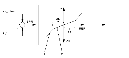
db determines the size of a dead zone in which the proportional action coefficient
gain is not effective, but rather a proportional action coefficient reduced by the parameter
gain_red. The parameter
db has an effect on the system deviation
ERR = SP - PV in the form shown in the illustration
Representation of the dead zone. Unnecessary actuator loads caused by small controlled variable disturbances or measurement noise can be reduced by the dead zone.
Enter the db parameter as positive.
Enter values between 0 and 1 for gain_red.
Tracking of manual value
YMAN
When manual tracking mode is enabled (ymanc = 1), the input YMAN is tracked to the manipulated variable value Y when in automatic and cascade modes, this means: YMAN = Y. If manual tracking mode is disabled (ymanc = 0), the YMAN value remains unchanged.
Representation of the dead zone
Dead zone:
1
Gradient 1
2
Gradient gain_red
Manipulated variable limiting
The limits ymax and ymin retain the manipulated variable within the prescribed range. Therefore ymin ≤ Y ≤ ymax.
The elements st_qmax and st_min signal that the manipulated variable has reached a limit, and thus been capped:
-
st_max = 1 if Y ≥ ymax
-
st_min = 1 if Y ≤ ymin.
For limiting the manipulated variable, the upper limit ymax should be greater than the lower limit ymin.
