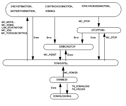
|
|
(Original Document)
|

|
Status
|
Corresponds to
|
|---|---|
|
Disabled
|
Idle or initial status of the axis.
|
|
Standstill
|
Waiting status of the axis, it is powered up and is error-free.
|
|
Discrete Motion
|
Discrete motion in progress.
|
|
Continuous Motion
|
Continuous motion in progress.
|
|
Synchronized Motion
|
Synchronized motion in progress.
|
|
MotionTask Motion
|
Current motion task program.
|
|
Downloading
|
Parameters or motion tasks currently being transferred between the PLC and the servodrive memory.
|
|
Homing
|
The axis is executing a homing.
|
|
Stopping
|
Valid during the execution of the axisí MC_STOP, the Done and the non-execution of MC_STOP brings the Axis_Ref to the Standstill status.
|
|
Errorstop
|
Valid during the axis stop due to an error, before the error has been acknowledged.
|