Introduction
You can install an M580 safety I/O module in any X Bus or Ethernet rack by placing it into any slot not reserved for the safety power supply or CPU (in the case of a local main rack).
You can hot swap M580 safety I/O.
General Cabling Precautions
To limit a DC load from interfering with an AC source, separate the power circuit cables (for example, cables leading to the power supply) from both input cables from sensors and output cables leading to actuators.
Place cables connecting the CPU to I/O modules in a sheath that is enclosed by metal ducting. Keep the sheathing for I/O cables separate from power cabling that is placed in its own sheathing. Place sheathed power cables in separate ducting from the I/O cables. Power cables and I/O cables need to be separated by a minimum distance of 100 mm.
Grounding Precautions
Each M580 safety I/O module is equipped with ground connection contacts.
Schneider Electric recommends the use of a BMXXSP•••• bar to help protect the rack from electromagnetic disturbances.
For the BMXSAI0410 safety analog input module, in particular, the use of a BMXXSP•••• bar is recommended. Connect the cable sheathing to the grounding bar by clamping it to the grounding bar on the module side.
| DANGER | |
|---|---|
Input Module Sensor Placement (In Relation to the Ground)
When placing sensors in your system:
Place sensors in close proximity to each other, separated by not more than a few meters.
Reference all sensors to a single point, and connect that point to the PAC ground.
Installing a Safety I/O Module in the Rack
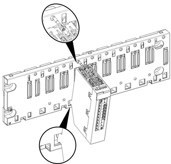
An M580 safety I/O modules requires a single rack slot. You can install a safety I/O module into any slot not reserved for the power supply or CPU. Follow these steps to install a safety I/O module in a rack:
Step |
Action |
|
|---|---|---|
1 |
Position the locating pins situated at the bottom rear of the module in the corresponding slots on the rack. |
 |
2 |
Swivel the module towards the top of the rack so that the module sits flush with the back of the rack. The module is now set in position. |
|
3 |
Tighten the single screw on top of the module to maintain the module in place on the rack. Tightening torque: 0.4...1.5 N•m (0.30...1.10 lbf-ft). |
|
4 |
For each additional module, repeat steps 1, 2, and 3 until all modules are installed on the rack. |
|
Grounding the I/O Modules
For information on grounding, refer to the topic Grounding the Rack and Power Supply Module.


