Introduction
The size and number of racks and the kinds of modules installed on the racks are significant considerations when you are planning an installation. That installation may be either inside or outside an enclosure. The height, width, and depth of the installed system head as well as the spacing between the local and the extender racks need to be well understood.
| WARNING | |
|---|---|
Modules such as the power supply, CPU, coprocessor, and I/O are cooled by natural convection. Install them on a horizontally installed rack as illustrated in this manual to maintain the necessary thermal cooling. Other rack mounting positions may cause overheating and unexpected equipment operation.
Rack Usage
The racks available in Control Expert, and their permitted usage, are described below:
Reference |
Slots |
Bus |
Usage |
|||
|---|---|---|---|---|---|---|
Local Main Rack |
Local Extended Rack |
Remote Main Rack |
Remote Extended Rack |
|||
BME racks: |
||||||
BME XBP 0400 |
4 |
XBus & Ethernet |
x |
x |
x |
x |
BME XBP 0800 |
8 |
XBus & Ethernet |
x |
x |
x |
x |
BME XBP 1200 |
12 |
XBus & Ethernet |
x |
x |
x |
x |
BME XBP 0602 |
6 |
XBus & Ethernet |
x |
x |
x |
x |
BME XBP 1002 |
10 |
XBus & Ethernet |
x |
x |
x |
x |
BMX racks: |
||||||
BMX XBP 0400 |
4 |
X Bus |
– |
x |
x |
x |
BMX XBP 0600 |
6 |
X Bus |
– |
x |
x |
x |
BMX XBP 0800 |
8 |
X Bus |
– |
x |
x |
x |
BMX XBP 1200 |
12 |
X Bus |
– |
x |
x |
x |
Premium racks: |
||||||
NOTE: Premium
racks are not supported by M580 safety PACs.
|
||||||
Quantum racks: |
||||||
140 XBP 002 00 |
2 |
Quantum |
– |
– |
x |
x |
140 XBP 003 00 |
3 |
Quantum |
– |
– |
x |
x |
140 XBP 004 00 |
4 |
Quantum |
– |
– |
x |
x |
140 XBP 006 00 |
6 |
Quantum |
– |
– |
x |
x |
140 XBP 010 00 |
10 |
Quantum |
– |
– |
x |
x |
140 XBP 016 00 |
16 |
Quantum |
– |
– |
x |
x |
X : Permitted – : Not permitted |
||||||
Clearance Around the Racks
Leave a minimum space of 12 mm (0.472 in.) on the right side of each rack for cooling.
When your plan calls for extender racks, leave a minimum space of 35 mm (1.378 in.) in front of the modules. The BMX XBE 1000 rack extender module requires this clearance for the local bus connector and terminator.
Spacing Requirements for an M580 CPU in a Local Main Rack
| WARNING | |
|---|---|
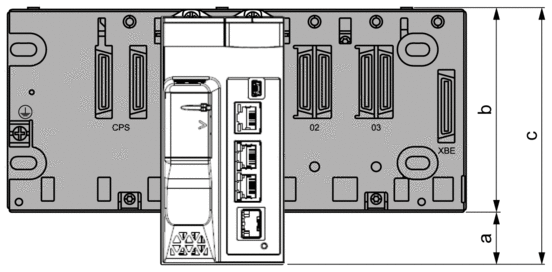
In the main local rack, allow additional clearance at the bottom of the rack for the CPU. This illustration shows the mounting dimensions when either an X Bus rack or an Ethernet rack is used. The overall height dimension of the main local rack in both cases is 134.6 mm (5.299 in.).

a Additional space below the rack to accommodate the height of the CPU. For an X Bus rack, the value is 32.0 mm (1.260 in.); for an Ethernet rack, the value is 30.59 mm (1.204 in.).
b The height of the rack. For an X Bus rack, the height is 103.7 mm (4.083 in.); for an Ethernet rack, the height is 105.11 mm (4.138 in.).
c The height of the main local rack, 135.7 mm (5.343 in.).
Thermal Considerations Inside an Enclosure
If the racks are installed in an enclosure, you need to facilitate air circulation. Use an enclosure that allows these minimum clearances:
80 mm (3.15 in.) above the top of the modules on the rack
60 mm (2.36 in.) below the bottom of the modules on the rack
60 mm (2.36 in.) between modules and wiring ducts
The minimum depth of the enclosure is:
150 mm (5.91 in.) if the rack is fastened to a plate
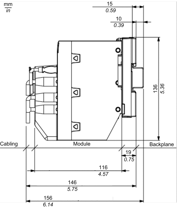
160 mm (6.30 in.) if the rack is mounted on a 15 mm (0.59 in.) DIN rail
If BMX XBE 1000 rack extender modules are connected, the use of BMX XBC •••K cables with connectors angled at 45° is recommended.
Here is a side view of a rack on a DIN rail with modules and cables mounted in an enclosure:

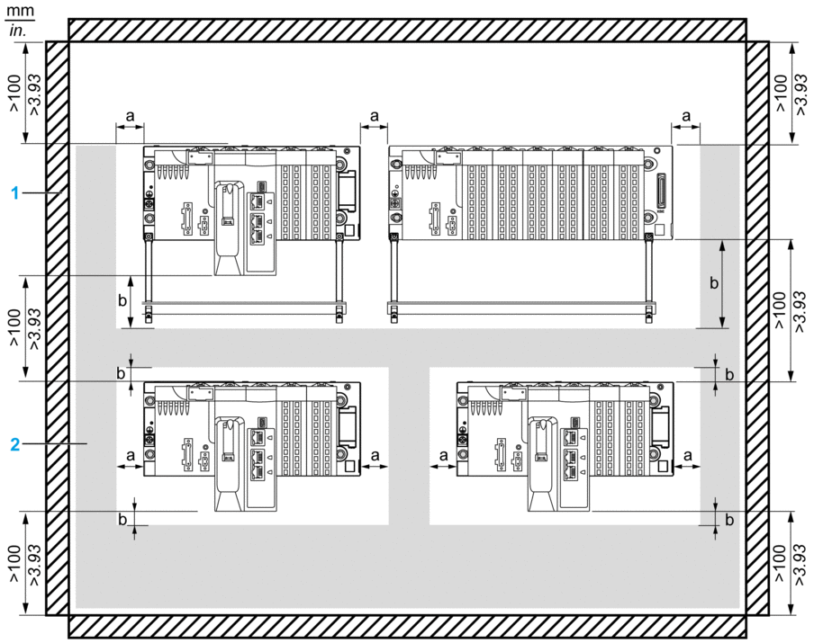
This illustration shows the rules of a typical installation in a cabinet with ducts:

1 installation or casing
2 wiring duct or tray
a side clearance: > 40 mm (1.57 in.)
b top and bottom clearance with surrounding objects: > 20 mm (0.79 in.)
There is no shielding bar, nor ducts between racks.
The spacing between racks is not less than 40 mm (1.57 in).
You apply a 5 °C (9 °F) derating to the maximum ambient temperature allowed. That is 55 °C (131 °F) for standard and coated module versions and 65 °C (149 °F) for hardened modules.


