Introduction
There are three RJ45 Ethernet ports on the front of the CPU: one service port, and two device network ports. The ports share the characteristics described below.
Common Characteristics
All three ports have the same RJ45 connector and all use the same type of Ethernet cables.
Dust Cover
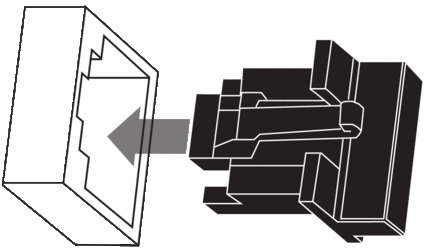
To keep dust from entering the unused Ethernet ports, cover the unused ports with the stopper:

Ethernet Ports
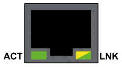
Each RJ45 connector has a pair of LED indicators:

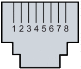
The pin positions, pinouts, and cable connections are the same on all three RJ45 Ethernet ports:
Pin |
Description |
|
|---|---|---|
1 |
TD+ |
Pinout:  |
2 |
TD- |
|
3 |
RD+ |
|
4 |
not connected |
|
5 |
not connected |
|
6 |
RD- |
|
7 |
not connected |
|
8 |
not connected |
|
— |
shell/chassis ground |
|
The ports have an auto MDIX capability that automatically detects the direction of the transmission.
Choose from these Ethernet cables to connect to the Ethernet ports:
TCSECN3M3M••••: Cat 5E Ethernet straight-through shielded cable, rated for industrial use, CE- or UL-compliant
TCSECE3M3M••••: Cat 5E Ethernet straight-through shielded cable, rated for industrial use, CE-compliant
TCSECU3M3M••••: Cat 5E Ethernet straight-through shielded cable, rated for industrial use, UL-compliant
The maximum length for a copper cable is 100 m. For distances greater than 100 m, use fiber optic cable. The CPU does not have any fiber ports on it. You may use dual ring switches or BMX NRP •••• fiber converter modules to handle the copper-fiber conversion.
Ethernet Ports on Standalone CPUs
On standalone CPUs, the ACTIVE LED is green. The LNK LED is either green or yellow, depending on the status:
LED |
LED Status |
Description |
|---|---|---|
ACTIVE |
OFF |
No activity is indicated on the Ethernet connection. |
ON / blinking |
Data is being transmitted and received on the Ethernet connection. |
|
LNK |
OFF |
No link is established at this connection. |
ON green |
A 100 Mbps link* is established at this connection. |
|
ON yellow |
A 10 Mbps link* is established at this connection. |
|
* The 10/100 Mbps links support both half-duplex and full-duplex data transfer and autonegotiation. |
||
Service Port
The service port is the uppermost of the three Ethernet ports on the front panel of the CPU. This port can be used:
To provide an access point that other devices or systems can use to monitor or communicate with the M580 CPU.
As a standalone DIO port that can support a star, or daisy chain topology of distributed equipment.
To mirror the CPU ports for Ethernet diagnostics. The service tool that views activity on the mirrored port may be a PC or an HMI device.
The service port may not provide full performance and features that the Device Network ports on the CPU provide.
Connecting the service port, either directly or through a switch/hub, to the device network may affect system performance.
Device Network Dual Ports
You may use a Device Network port to support a star or daisy chain topology of distributed equipment. You may use both Device Network ports to support a ring topology.
When used as RIO ports, both ports connect the CPU to the main ring in an Ethernet daisy-chain loop or ring.
For more information about RIO/DIO architectures, refer to chapter Modicon M580 System.
Grounding Considerations
Follow all local and national safety codes and standards.
| DANGER | |
|---|---|


