Introduction
When designing a safe application, you will need to follow the recommendation of one of the safety standard which apply to your application domain. Most of the application standards derive from or are linked to the generic standard IEC 61508 including, for example, the process industry standard (IEC 61511), the machine industry standards (IEC 62061 and ISO 13489), the nuclear industry standard (IEC 61513), the railway standards (EN 5012x), and so forth.
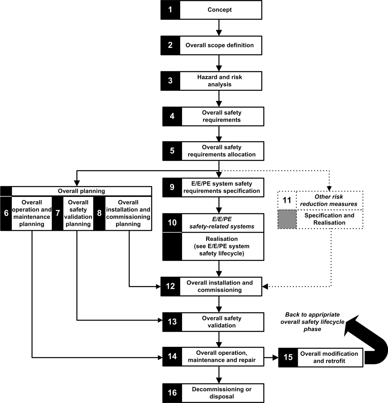
IEC 61508 defines an application life cycle with a sequence of steps. Each step has a defined role, needs mandatory input documents, and produces output documents. The decision to use a safety integrated system (SIS) is made at the end of the Safety Requirements Allocation step (step 5).
This topic defines the necessary checks, related to the usage of a M580 safety system, that you need to perform at the following steps:
| 9. | E/E/PE System safety requirements specification |
| 10. | E/E/PE Safety related systems realisation |
| 12. | Overall installation and commissioning |
| 13. | Overall safety validation |
| 14. | Overall operation, maintenance and repair |
| 15. | Overall modification and retrofit |
The following diagram presents the overall safety lifecycle:

Step 9: E/E/PE System safety requirements specification
This step takes place when the risk analysis is completed and has provided, among other things, the following information:
Definition of the safety integrated functions
Their required performances (time, risk reduction, SIL…)
Their failure modes
It should produce the safety requirement specifications which will include, at least, the following information necessary to design a safe application using any type of safety PAC:
Safe state of the safety integrated functions
SIS operating mode analysis (including the behavior in run, stop, power on sequence, maintenance, repair…)
Test interval of the SIF
MTTR of the SIS
Choice of energized or de-energized SIF
Performance of the logic solver (reaction time, precision …)
Performance requirements
Fault tolerance
Integrity
Maximum spurious trip rate
Maximum dangerous fault rate
Environmental specification (EMC, mechanical, chemical, climate…)
Step 10: E/E/PE Safety related systems realisation
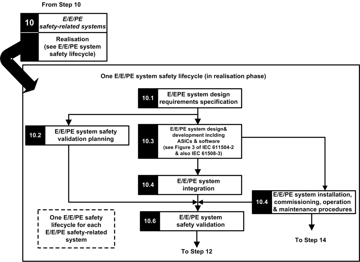
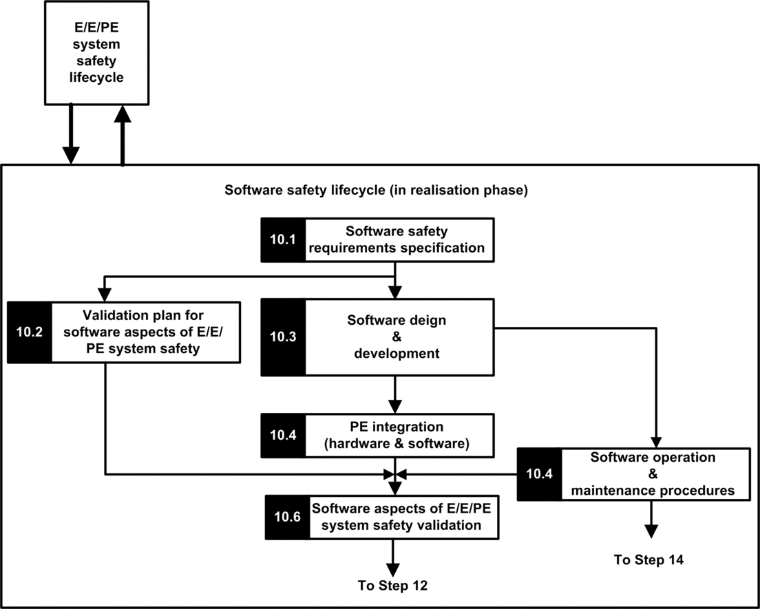
The IEC 61508 divide this step into 2 sub life cycles, one for the system realisation, one for the software realisation.
System realisation:

Software realisation:

The goal of the first sub steps (10.1) is to convert the SIS safety requirements into specification of the hardware design, hardware tests, software design, software tests and integration tests. It should provide at least the following information necessary to design a safe application using safety M580:
Hardware architecture taking care of:
The respect of M580 rules about mixing non safety and safety modules: all the safety modules (safe IO modules and safe CPU/COPRO) are placed in racks where the main rack and its extension are powered by safe power supply and contains only safe modules or non-interfering modules of type 1.
Electric consumption per rack.
Derating rules.
Power supply architecture:
Only SELV/PELV power supply.
Software architecture:
Including the usage of M580 global variables; a global variable should not prevent a safety action to be triggered unless a “safe application protocol” is used.
Hardware integration (cabling, cabinet, and so forth):”
Fuse protection.
Accessories for wire diagnostic.
Human machine interfaces:
Including the usage of M580 global variables; a global variable should not prevent a safety action to be triggered unless a “safe application protocol” is used.
Electric/numerical interfaces:
Safe state.
Sensor and actuator.
Algorithm
Performances (including task period, watchdog and timeout definition) and prediction of a good behavior using the formula:
 NOTE: The formula is applicable only when MAST task is not in cyclic mode.
Behavior in case of:
Unlock configuration
Maintenance mode
Maintenance input
Invalid channel
Wiring failure
Channel health
Module health
Management of the UID of the safe IO modules (define when a UID should be changed).
NTP server:
Choice of PAC as NTP server or external NTP server (depending on the usage of I/O time stamping in the process application).
Server redundancy
Server loss
The next sub steps refine the specifications into technical detailed specification, perform the design itself execute all the test plans and provides the reports.
Step 12: Overall installation and commissioning
The goal of this step is to define the requirements for installation, task planning, tooling, commissioning procedure and then build the system and verify its correctness.
For Hot Standby applications, verify that the fallback timeout of the safety output modules fits the conditions defined for swap and switchover operations, and verify the CRA hold-up time.
Verify that fallback safety timeout (S_TO) for the safety output modules is, at least, greater than the greater of 40 ms or (2.5 * TSAFE), where TSAFE equals the configured SAFE task period.
Clear any pre-existing application inside the PLC, or use an application configured with no CIP safety devices before installing the safety device onto an Ethernet safety network (with CIP safety devices).
In an M580 safety system, the commissioning procedure should include the following points:
Verify Control Expert integrity, verify Control Expert version.
Correctness of the CPU and Coprocessor firmware versions by supervising the system words %SW14 (Firmware version of PLC processor) and %SW142 (Firmware version of coprocessor).
Correctness of each module addresses (position in rack, CRA switches).
Correctness of the cabling:
Point to point verification: from internal variable to IO module and to actuator/sensor.
Fuses.
Equipment for wiring diagnostic.
At the end of the procedure, all the safety modules are in “lock” mode (it is recommended that the safe application itself checks this condition).
Correctness of each module configuration (including the timeouts):”
Read the configuration using the Control Expert screen and compare to specification.
All the safety applications have been rebuilt using the option, then downloaded to each PLC, and their SAId saved as well as the application archive.
The task period and task watchdog are correct.
Module references and version.
Usage of SELV/PELV only.
If CIP Safety devices are used in the safety application:
The Safety Configuration ID signature (SCID) can be considered to be verified (option enabled in Control Expert CIP Safety DTM) and target configuration locked after user testing.
To confirm that the originator configuration created by the user with the Control Expert software tool was correctly sent to and saved in the M580 CIP Safety originator, visually compare all the CIP Safety target configuration parameter values displayed in the target DDDTs (in connected mode with the PAC, using an Animation table) with the parameter values displayed and configured in the target DTM Configuration verification tab. All of the values need to be identical.
Test all safety connection configurations after they are applied in the M580 CIP Safety originator to confirm that each target connection is operating as intended.
Before installing the CIP Safety devices into the safety network, commission all the safety devices with MacId and Baud Rate as necessary.
User testing is the means by which all application downloads are validated
Step 13: Overall safety validation
The goal of this step is to prove that the safety integrated system fulfills its requirements. It executes all the tests and produce the reports define in the step 7 of the “safety lifecycle”. It should include:
Verify that there is no overrun condition during any of the system state (verification of the system bit %S19 in the MAST, FAST, AUX0 tasks), and that the max and current SAFE task execution time (%SW42 and %SW43) are below the SAFE task Period.
Verify the CPU load formula:
 NOTE: You can use the system words %SW110 to %SW115 to perform a real-time evaluation of the average load for CPU tasks (if all tasks are periodic, %SW116 should be less than 80).
Verify the special operating modes (module unlock, maintenance input, invalid channel, wiring defect).
For Hot Standby applications, verify that all tasks are correctly synchronized through the Hot Standby link by checking and using the MAST_SYNCHRONIZED, FAST_SYNCHRONIZED, and SAFE-SYNCHRONIZED bits in the T_M_ECPU_HSBY DDT. Refer to the Modicon M580 Hot Standby, System Planning Guide for Frequently Used Architectures for a description of the T_M_ECPU_HSBY DDT.
Step 14: Overall operation, maintenance and repair
Execute the proof tests at the right period.
Monitor the SAId see note.
NOTE: As long as the SAId has not changed, the safety portion of the application has not been changed. Refer to the S_SYST_STAT_MX function block for details on SAId behavior.Monitor the configuration lock status of each safety module.
Record the repair operations.
If a module is replaced, the replacement device needs to be configured properly and you (the user) need to verify its operation. Execute (at minimum) the commissioning operations related to this module.
Record the deviations.
Step 15: Overall modification and retrofit
Any modification should be treated as a new design. An impact analysis may help to define the part of the former safety system that can be kept and the part that must be designed again.


