Introduction
You can configure the BMXSRA0405 safety digital output relay module to achieve either SIL2 Category 2 (Cat2) / Performance Level c (PLc) or SIL3 Cat4 / PLe compliance in different ways, depending on:
the number of outputs the module will support, and
how you want to test the ability of the module to place the actuator into the intended demand state, either:
automatically by the module (in this case, there is no state transition for the actuator) or
by means of a procedure that performs and checks a daily transition of the signal from the module to the actuator (in this case, the transition impacts the actuator state).
Make this configuration by selecting an application number (described in the tables, below) in the list in the module tab in Control Expert.
SIL2 Cat2 / PLc wiring design applications:
Function |
Demand State |
Relays |
Outputs |
Signal Test? |
Wiring Diagram (see below) |
|
|---|---|---|---|---|---|---|
Automatic Signal Test?1 |
Daily Signal Transition? |
|||||
Application_1 |
De-energized |
1 |
4 |
No |
Yes |
A |
Application_2 |
De-energized |
2 |
2 |
Yes |
No |
B |
Application_3 |
Energized |
1 |
4 |
No |
Yes |
A |
Application_4 |
Energized |
2 |
2 |
Yes |
No |
C |
1. The automatic signal test does not impact the actuator state. |
||||||
SIL3 Cat4 / PLe wiring design applications:
Function |
Demand State |
Relays |
Outputs |
Signal Test? |
Wiring Diagram (see below) |
|
|---|---|---|---|---|---|---|
Automatic Signal Test?1 |
Daily Signal Transition? |
|||||
Application_5 |
De-energized |
2 |
2 |
No |
Yes |
C |
Application_6 |
De-energized |
4 |
1 |
Yes |
No |
D |
Application_7 |
Energized |
2 |
2 |
No |
Yes |
C |
Application_8 |
Energized |
2 |
2 |
Yes |
No |
C |
1. The automatic signal test does not impact the actuator state. |
||||||
Each of these eight application selections are described in the following wiring examples.
Application_1: 4 Outputs, SIL2 / Cat2 / PLc, De-energized State, No Automatic Signal Test
The demand state for this application design is de-energized. If the module detects an internal error for an output, it de-energizes that output.
| CAUTION | |
|---|---|
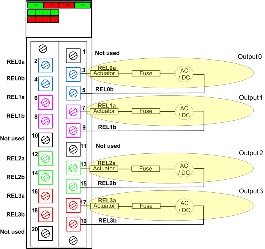
Refer to wiring diagram A, below, for a depiction of the wiring design for Application_1.
Application_2: 2 Outputs, SIL2 Cat2 / PLc, De-energized State, Automatic Signal Test
The demand state for this application design is de-energized. If the module detects an internal output error on one of the relays used for an output, it de-energizes both relays (Relay 0 and Relay 1 or Relay 2 and Relay 3) for that output.
Your application program needs to command the same output state to all relays that activate the same actuator.
The module sequentially performs an automatic periodic pulse test on each relay. The duration of the test is less than 50 ms. Because of the configuration of the two relays used (in parallel), the test has no impact on the output load (normally energized). You can configure the frequency of the test by setting the in the tab of the module. Valid test frequency values range from1...1440 minutes.
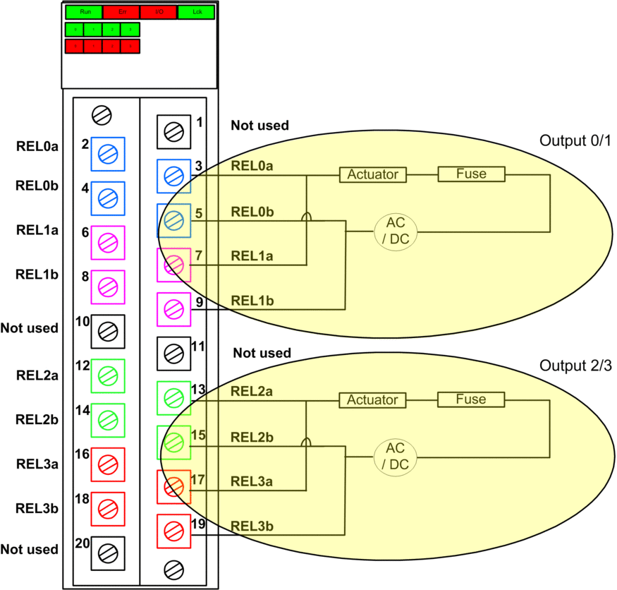
Refer to wiring diagram B, below, for a depiction of the wiring design for Application_2.
Application_3: 4 Outputs, SIL2 / Cat2 / PLc, Energized State, No Automatic Signal Test
The demand state for this application design is energized. If the module detects an internal error for an output, it de-energizes that output, which is the safe state.
| CAUTION | |
|---|---|
Refer to wiring diagram A, below, for a depiction of the wiring design for Application_3.
Application_4: 2 Outputs, SIL2 Cat2 / PLc, Energized State, Automatic Signal Test
The demand state for this application design is energized. If the module detects an internal output error on one of the relays used for an output, it de-energizes both relays (Relay 0 and Relay 1 or Relay 2 and Relay 3) for that output.
Your application program needs to command the same output state to all relays that activate the same actuator.
The module sequentially performs a periodic pulse test on each relay. The duration of the test is less than 50 ms. Because of the configuration of the two relays used (in parallel), the test has no impact on the output load (normally energized). You can configure the frequency of the test by setting the in the tab of the module. Valid test frequency values range from1...1440 minutes.
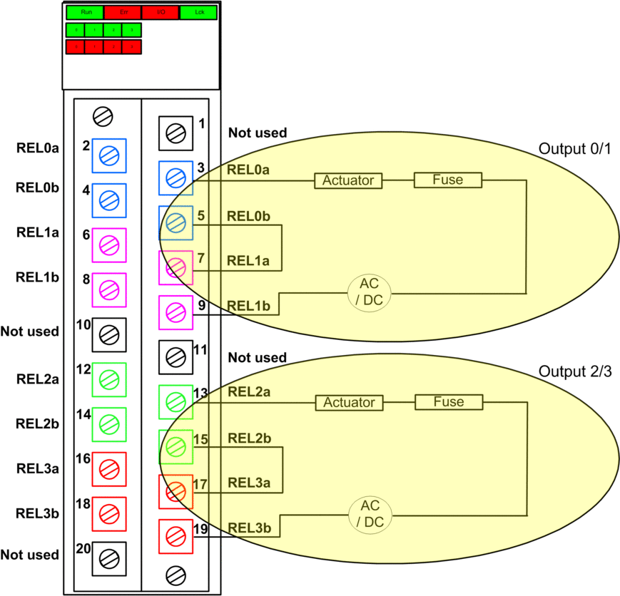
Refer to wiring diagram C, below, for a depiction of the wiring design for Application_4.
Application_5: 2 Outputs, SIL3 / Cat4 / PLe, De-energized State, No Automatic Signal Test
The demand state for this application design is de-energized. If the module detects an internal output error on one of the relays used for an output, it de-energizes both relays (Relay 0 and Relay 1 or Relay 2 and Relay 3) for that output.
Your application program needs to command the same output state to all relays that activate the same actuator.
| CAUTION | |
|---|---|
Refer to wiring diagram C, below, for a depiction of the wiring design for Application_5.
Application_6: 1 Output, SIL3 / Cat4 / PLe, De-energized State, Automatic Signal Test
The demand state for this application design is de-energized. If the module detects an internal output error on one of the relays used for an output, it de-energizes all relays (Relay 0, Relay 1, Relay 2, and Relay 3) for the module.
Your application program needs to command the same output state to all relays that activate the same actuator.
The module sequentially performs a periodic pulse test on each relay. The duration of the test is less than 50 ms. Because of the configuration of the four relays used (2 pair of two serial relays set in parallel), the test has no impact on the output load (normally energized). You can configure the frequency of the test by setting the in the tab of the module. Valid test frequency values range from1...1440 minutes.
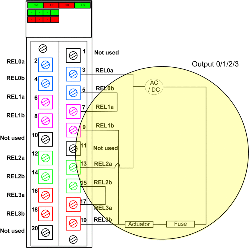
Refer to wiring diagram D, below, for a depiction of the wiring design for Application_6.
Application_7: 2 Outputs, SIL3 / Cat4 / PLe, Energized State, No Automatic Signal Test
The demand state for this application design is energized. If the module detects an internal output error on one of the relays used for an output, it de-energizes both relays (Relay 0 and Relay 1 or Relay 2 and Relay 3) for that output.
Your application program needs to command the same output state to all relays that activate the same actuator.
| CAUTION | |
|---|---|
Refer to wiring diagram C, below, for a depiction of the wiring design for Application_7.
Application_8: 2 Outputs, SIL3 Cat4 / PLe, Energized State, Automatic Signal Test
The demand state for this application design is energized. If the module detects an internal output error on one of the relays used for an output, it de-energizes both relays (Relay 0 and Relay 1 or Relay 2 and Relay 3) for that output.
Your application program needs to command the same output state to all relays that activate the same actuator.
The module sequentially performs a periodic pulse test on each relay. The duration of the test is less than 50 ms. Because of the configuration of the two relays used (in serial), the test has no impact on the output load (normally de-energized). You can configure the frequency of the test by setting the in the tab of the module. Valid test frequency values range from1...1440 minutes.
Refer to wiring diagram C, below, for a depiction of the wiring design for Application_8.
Wiring Diagram A
This wiring diagram applies to Application_1 and Application_3:

Wiring Diagram B
This wiring diagram applies to Application_2:

Wiring Diagram C
This wiring diagram applies to Application_4, Application_5, Application_7 and Application_8:

Wiring Diagram D
This wiring diagram applies to Application_6:


