Introduction
The BMXSRA0405 digital relay output module includes 4 relays and supports up to 4 outputs. The module presents a pair of a and b pins for each relay. Note that for each relay:
the two a pins are internally connected, and
the two b pins also are internally connected.
Terminal Blocks
You can use the following Schneider Electric 20-point terminal blocks to fit the 20 pin connector on the front of the module:
screw clamp terminal block BMXFTB2010
age clamp terminal block BMXFTB2000
spring type terminal block BMXFTB2020
Process Power Supply
You need to install the appropriate 24 Vdc or 24 Vac to 230 Vac process power supply.
Fuse
A fast blow fuse, maximum of 6 A, that is suitable for the selected application and relay design is required. Always install an external fuse in series with the external power supply, the relay, and the load.
| WARNING | |
|---|---|
Wiring Connector
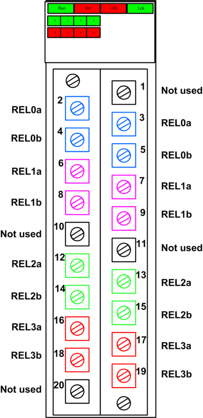
The following example presents the pins on the relay module:

Mapping Inputs to Connector Pins
The following provides a description of each pin on the BMXSRA0405 digital relay output module:
Pin Description |
Pin Number on Terminal Block |
Pin Description |
|
|---|---|---|---|
NO contact, Relay 0a |
2 |
1 |
Not used |
NO contact, Relay 0b |
4 |
3 |
NO contact, Relay 0a |
NO contact, Relay 1a |
6 |
5 |
NO contact, Relay 0b |
NO contact, Relay 1b |
8 |
7 |
NO contact, Relay 1a |
Not used |
10 |
9 |
NO contact, Relay 1b |
NO contact, Relay 2a |
12 |
11 |
Not used |
NO contact, Relay 2b |
14 |
13 |
NO contact, Relay 2a |
NO contact, Relay 3a |
16 |
15 |
NO contact, Relay 2b |
NO contact, Relay 3b |
18 |
17 |
NO contact, Relay 3a |
Not used |
20 |
19 |
NO contact, Relay 3b |


