Introduction
You can wire the BMXSDO0802 safety digital output module to actuators to achieve SIL3 Category 4 (Cat4) / Performance Level e (PLe) compliance in different ways, depending on your requirements for high availability.
| CAUTION | |
|---|---|
The following SIL3 Cat4/PLe digital output application wiring examples are described, below:
Cat4/PLe:
a single output module channel commanding one process variable. A single actuator is employed in this design.
Cat4/PLe with high availability:
two redundant output modules, each with a channel connected to a separate actuator, but commanding the same process variable.
| CAUTION | |
|---|---|
Configurable Wiring Diagnostics in Control Expert
For the BMXSDO0802 safety digital output module, use its page in Control Expert to:
Enable for each energized channel. This test performs the following actuator wiring diagnostics for a channel:
Short circuit to 24 Vdc detection
Crossed circuit detection between two output channels
Enable for each of eight channels, which performs the following wiring diagnostics for that channel:
Open (or cut) wire detection (i.e. the output channel is not connected to the actuator)
Short circuit wiring detection to the 0 Vdc ground
Enable the for each output channel. This test is performed periodically when the output is in the de-energized state, and applies a pulse (duration less than 1 ms) to the output to determine if it can transition to the energized state. If the current exceeds a threshold of 0.7 A, the output is reported as being in a short circuit condition with the 0 Vdc ground. The test period is less than 1 s.
| WARNING | |
|---|---|
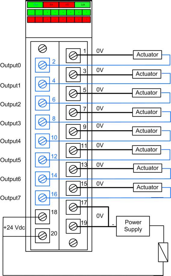
SIL 3 Cat4/PLe - Single Digital Output Module Example
The following example presents one exclusive actuator wired to each output on a single output module. Each loop is SIL 3 Cat4/PLe:

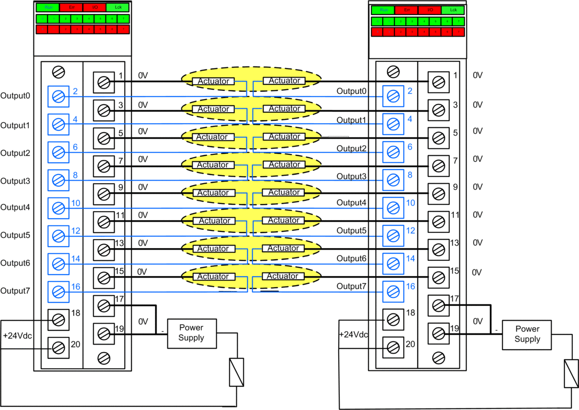
SIL 3 Cat4/PLe - High Availability Example:
In the following wiring diagram, two redundant outputs command the same process variable. As displayed below, each output is connected to separate actuators, then each actuator executes the same command sent over different channels. Alternatively, the two redundant outputs could be wired together to command the same actuator.

Output Wiring Diagnostic Summary
The two designs provide the following wiring diagnostics:
Condition |
Diagnostic Provided in Output State? |
|
|---|---|---|
Energized |
De-energized |
|
Open (or cut) wire1 |
Yes. Diagnosed each cycle. |
Yes. Diagnosed each cycle. |
Output in overload2 |
Yes. Diagnosed each cycle. |
No. |
Short circuit to the 0 V ground |
Yes. Diagnosed each cycle. |
Yes. Diagnostic period < 1 s. |
Short circuit to the 24 Vdc1 |
Yes. Diagnostic period < 1 s. |
Yes. Diagnosed each cycle. |
Crossed circuits between two channels |
Yes. Diagnostic period < 1 s. |
Yes. Diagnosed each cycle. |
1. This diagnostic function is performed if enabled in the module tab in Control Expert. 2. After the condition is resolved, re-arm the output by de-energizing it. |
||
| WARNING | |
|---|---|
| WARNING | |
|---|---|
| WARNING | |
|---|---|
| WARNING | |
|---|---|
| WARNING | |
|---|---|
| WARNING | |
|---|---|


