Introduction
The BMXSDO0802 digital output module presents a single group of 8 outputs.
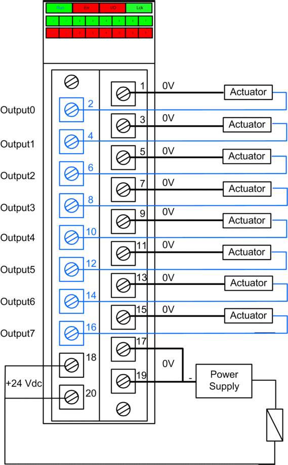
Both common +24 Vdc power supply pins (18 and 20) are internally connected.
All common 0 V pins (1, 3, 5, 7, 9, 11, 13, 15, 17 and 19) are internally connected.
Terminal Blocks
You can use the following Schneider Electric 20-point terminal blocks to fit the 20 pin connector on the front of the module:
screw clamp terminal block BMXFTB2010
age clamp terminal block BMXFTB2000
spring type terminal block BMXFTB2020
Process Power Supply
A 24 Vdc protected extra low voltage (SELV/PELV) overvoltage category II process power supply is required. Schneider Electric recommends a power supply that does not automatically restore power after a power interruption.
Fuse
A fast blow fuse, maximum of 6 A, is required to help protect the external power supply against short-circuit and over voltage conditions.
| CAUTION | |
|---|---|
Wiring Connector Pins
The following wiring diagram presents a single output module connected to 8 actuators:

Mapping Outputs to Connector Pins
The following provides a description of each pin on the BMXSDO0802 output module:
Pin Description |
Pin Number on Terminal Block |
Pin Description |
|
|---|---|---|---|
Output 0 |
2 |
1 |
Common 0V |
Output 1 |
4 |
3 |
Common 0V |
Output 2 |
6 |
5 |
Common 0V |
Output 3 |
8 |
7 |
Common 0V |
Output 4 |
10 |
9 |
Common 0V |
Output 5 |
12 |
11 |
Common 0V |
Output 6 |
14 |
13 |
Common 0V |
Output 7 |
16 |
15 |
Common 0V |
24 Vdc Process Power Supply |
18 |
17 |
Common 0V |
24 Vdc Process Power Supply |
20 |
19 |
Common 0V |


