

Introduction
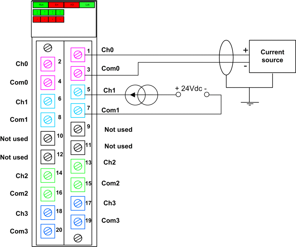
The BMXSAI0410 analog input module includes 4 analog inputs. The module presents two pair of pins – two positive channel (Ch) pins and two negative common (Com) pins – for each input.
For each input:
the two channel pins (Chn) are internally connected, and
the two common pins (Comn) also are internally connected.
To connect an analog sensor to an input, you can use either channel pin and either common pin for that input.
Terminal Blocks
You can use the following Schneider Electric 20-point terminal blocks to fit the 20 pin connector on the front of the module:
screw clamp terminal block BMXFTB2010
age clamp terminal block BMXFTB2000
spring type terminal block BMXFTB2020
Wiring Connector
The following example presents a generic wiring scheme for inputs on the module:
OOR element of the T_U_ANA_SIS_CH_IN structure
to “1”.Mapping Inputs to Connector Pins
The following provides a description of each pin on the BMXSAI0410 analog input module:
Pin Description |
Pin Number on Terminal Block |
Pin Description |
|
|---|---|---|---|
Input (+) of channel 0 |
2 |
1 |
Input (+) of channel 0 |
Input (–) of channel 0 |
4 |
3 |
Input (–) of channel 0 |
Input (+) of channel 1 |
6 |
5 |
Input (+) of channel 1 |
Input (–) of channel 1 |
8 |
7 |
Input (–) of channel 1 |
Not used |
10 |
9 |
Not used |
Not used |
12 |
11 |
Not used |
Input (+) of channel 2 |
14 |
13 |
Input (+) of channel 2 |
Input (–) of channel 2 |
16 |
15 |
Input (–) of channel 2 |
Input (+) of channel 3 |
18 |
17 |
Input (+) of channel 3 |
Input (–) of channel 3 |
20 |
19 |
Input (–) of channel 3 |
For example, to connect an analog sensor to input channel 0, you can connect:
Positive wire of the sensor to either pin 1 or pin 2.
Negative wire of the sensor to either pin 3 or pin 4.