Introduction
You can wire the BMXSDI1602 safety digital input module to sensors to achieve SIL3 compliance in several different ways, depending on:
the required Category (Cat2 or Cat4) and Performance Level (PLd or PLe) standard
your application’s requirements for high availability
| CAUTION | |
|---|---|
The following SIL3 digital input application wiring examples are described, below:
Cat2/PLd:
a single sensor wired to one input
Cat2/PLd with high availability:
a single sensor wired to two input points on different input modules
two sensors wired to two input points on different input modules
Cat4/PLe:
a single sensor wired to two input points on the same input module
two sensors, each wired to a different input point on the same input module
Cat4/PLe with high availability:
two sensors, each wired to two input different input points on different input modules
Configurable Wiring Diagnostics in Control Expert
For the BMXSDI1602 safety digital input module, use its page in Control Expert to:
Enable for each energized channel. This test performs the following actuator wiring diagnostics for a channel:
Short circuit to 24 Vdc detection.
Crossed circuit detection between two output channels.
The principle is to provide power to the sensors, by group of 8 channels (with VS1 for channels 0 to 3 (Rank A & B) and VS2 for channels 4 to 7 (Rank A & B)). A pulse to OFF is applied to these power outputs periodically with a period less than 1 second and a duration less than 1 ms. During this pulse, if the current read into the input is not null, the module considers the input in short-circuit.
Enable for each of eight channels, which performs the following wiring diagnostics for that channel:
Open (or cut) wire detection (i.e. the input channel is not connected to the sensor).
Short circuit wiring detection to the 0 Vdc ground.
The principle is to create artificially, then measure, a leakage current (Ileakage) on the line (with a resistor in parallel to the sensor) when sensor is opened. If this leakage current (0.4 mA <Ileakage < 1.3 mA) cannot be measured on the input line by the module, the external line is considered as cut (or in a short-circuit to ground condition). The diagnostic is performed with a period less than 10 ms.
For a dry contact sensor, we recommend that you set in parallel with the sensor a 33 K Ω resistor.
Using DDP 2 or 3 wires, the leakage current needs to fall within the limits defined above. You need to define the value of the resistor to set in parallel with the sensor, considering the natural leakage current of the sensor and the internal resistor of the input (7.5 K Ω).
| WARNING | |
|---|---|
SIL3 Cat2/PLd
Single sensor connected with one input, supplied by internal VS:
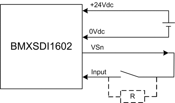
In this example, if internal power is supplied via:
VS1, use channels 0...3 ranks A & B.
VS2, use channels 4...7 ranks A & B.
Because the sensor is supplied power internally via a VS pin, the following channel wiring diagnostics apply:
Condition |
Detectable? |
Typical Detection Time |
|---|---|---|
Open (or cut) wire1 |
Yes |
< 10 ms |
Short circuit to the 0 V ground |
Yes |
|
Short circuit to the 24 Vdc1 |
Yes |
< 1 s |
Crossed circuits between two channels1 |
Yes |
|
1. This diagnostic function is performed if enabled in the module tab in Control Expert. |
||
| WARNING | |
|---|---|
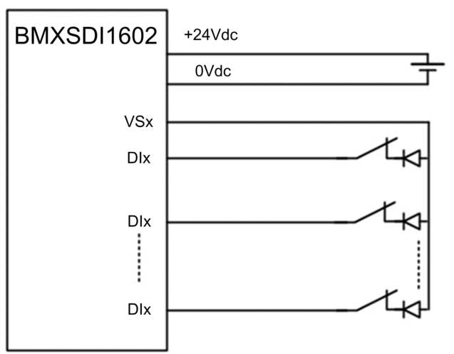
Single sensor connected with one input, powered by external power:
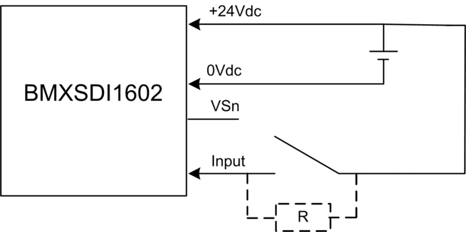
Because the sensor is supplied power externally, the following channel wiring diagnostics apply:
Condition |
Detectable? |
Typical Detection Time |
|---|---|---|
Open (or cut) wire1 |
Yes |
< 10 ms |
Short circuit to the 0 V ground |
Yes |
|
Short circuit to the 24 Vdc |
No |
– |
Crossed circuits between two channels |
No |
|
1. This diagnostic function is performed if enabled in the module tab in Control Expert. |
||
| WARNING | |
|---|---|
| WARNING | |
|---|---|
SIL3 Cat2/PLd with High Availability
Single sensor connected on 2 inputs powered by external power:
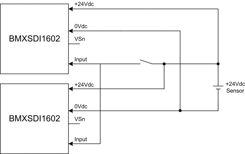
Because the single sensor is supplied power externally, the following channel wiring diagnostics apply:
Condition |
Detectable? |
Typical Detection Time |
|---|---|---|
Open (or cut) wire1 |
No |
– |
Short circuit to the 0 V ground |
No |
|
Short circuit to the 24 Vdc1 |
No |
|
Crossed circuits between two channels |
No |
|
1. This diagnostic function is performed if enabled in the module tab in Control Expert. |
||
| WARNING | |
|---|---|
| WARNING | |
|---|---|
2 redundant sensors connected on single inputs of 2 modules using VS:
The following example presents two redundant sensors (which may or may not be linked mechanically) that are used to acquire the same process variable. Each sensor is wired to a single input point on a different input module, with power supplied by the monitored VS power supply:
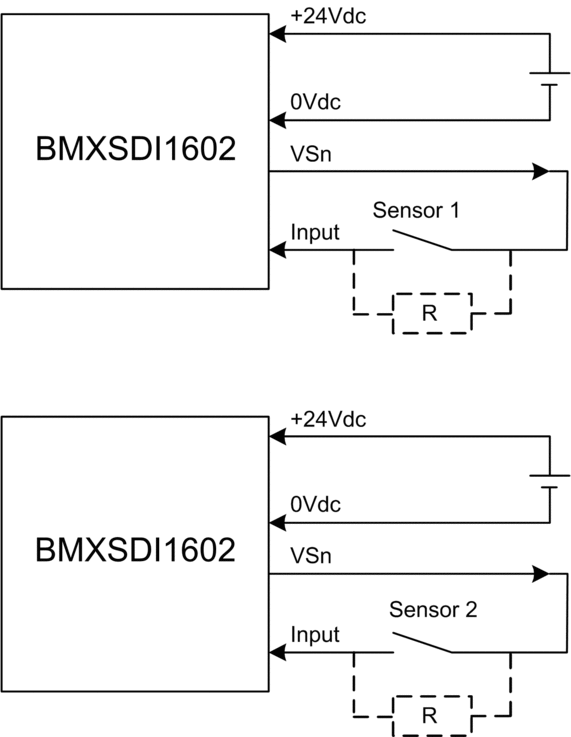
In this example, if internal power is supplied via:
VS1, use channels 0...3 ranks A & B.
VS2, use channels 4...7 ranks A & B.
In this design, you could use the
S_DIHAfunction block to manage the two input signals.Consider adding a Shottky diode to the input loop, between the sensor and the input point, to reduce the likelihood that a short circuit to 24 Vdc condition on one channel might cause the same condition on an adjacent channel.
Because the sensor is supplied power internally via a VS pin, the following channel wiring diagnostics apply:
Condition |
Detectable? |
Typical Detection Time |
|---|---|---|
Open (or cut) wire1 |
Yes |
< 10 ms |
Short circuit to the 0 V ground |
Yes |
|
Short circuit to the 24 Vdc1 |
Yes |
< 1 s |
Crossed circuits between two channels |
Yes |
|
1. This diagnostic function is performed if enabled in the module tab in Control Expert. |
||
| WARNING | |
|---|---|
2 redundant sensors connected on single inputs of 2 modules using external power:
Because the sensor is supplied power internally via a VS pin, the following channel wiring diagnostics apply:
Condition |
Detectable? |
Typical Detection Time |
|---|---|---|
Open (or cut) wire1 |
Yes |
< 10 ms |
Short circuit to the 0 V ground |
Yes |
|
Short circuit to the 24 Vdc |
No |
– |
Crossed circuits between two channels |
No |
|
1. This diagnostic function is performed if enabled in the module tab in Control Expert. |
||
| WARNING | |
|---|---|
| WARNING | |
|---|---|
Cat4/PLe
Single sensor connected on 2 inputs of same module using Vs:
The following example presents a single sensor wired to two input points on the same input module, with power supplied by the monitored VS power supply:
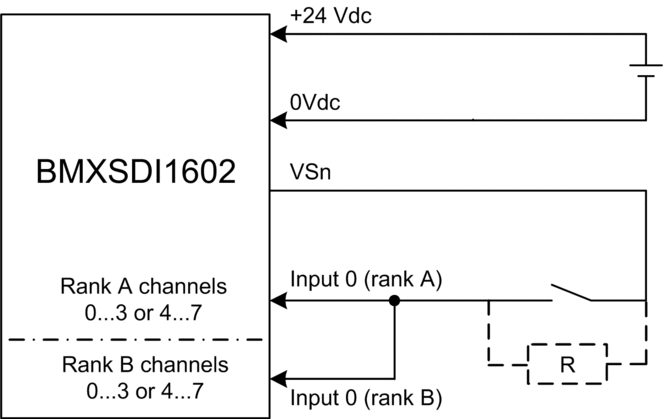
In this example, if internal power is supplied via:
VS1, use channels 0...3 ranks A & B.
VS2, use channels 4...7 ranks A & B.
In this design, you could use the
S_EQUIVALENTfunction block to manage the two input signals.Consider adding a Shottky diode to the input loop, between the sensor and the input point, to reduce the likelihood that a short circuit to 24 Vdc condition on one channel might cause the same condition on an adjacent channel.
Wiring diagnostic with single sensor connected on two inputs, using power from the VS pin:
Condition |
Detectable? |
Typical Detection Time |
|---|---|---|
Open (or cut) wire1 |
Yes |
< 10 ms |
Short circuit to the 0 V ground |
Yes |
|
Short circuit to the 24 Vdc1 |
Yes |
< 1 s |
Crossed circuits between two channels |
Yes |
|
1. This diagnostic function is performed if enabled in the module tab in Control Expert. |
||
| WARNING | |
|---|---|
Single sensor connected on 2 inputs of same module using external power supply:
Wiring diagnostic with single sensor connected on two inputs, using external power:
Condition |
Detectable? |
Typical Detection Time |
|---|---|---|
Open (or cut) wire1 |
Yes |
< 10 ms |
Short circuit to the 0 V ground |
Yes |
|
Short circuit to the 24 Vdc1 |
No |
– |
Crossed circuits between two channels |
No |
|
1. This diagnostic function is performed if enabled in the module tab in Control Expert. |
||
| WARNING | |
|---|---|
| WARNING | |
|---|---|
Non-equivalent sensor connected on 2 non-equivalent inputs of same module using Vs:
The following example presents a single non-equivalent sensor wired to two input points on the same input module, with power supplied by the monitored VS power supply. The module performs a 1oo2D evaluation:
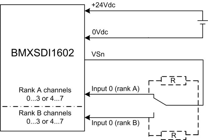
In this example, if internal power is supplied via:
VS1, use channels 0...3 ranks A & B.
VS2, use channels 4...7 ranks A & B.
In this design, you could use the
S_ANTIIVALENTfunction block to manage the two input signals.Consider adding a Shottky diode to the input loop, between the sensor and the input point, to reduce the likelihood that a short circuit to 24 Vdc condition on one channel might cause the same condition on an adjacent channel.
Wiring diagnostic with single non-equivalent sensors connected on two inputs, using power from the VS pin:
Condition |
Detectable? |
Typical Detection Time |
|---|---|---|
Open (or cut) wire1 |
Yes |
< 10 ms |
Short circuit to the 0 V ground |
Yes |
|
Short circuit to the 24 Vdc1 |
Yes |
< 1 s |
Crossed circuits between two channels |
Yes |
|
1. This diagnostic function is performed if enabled in the module tab in Control Expert. |
||
Non-equivalent sensor connected on 2 non-equivalent inputs of same module using external power:
Wiring diagnostic with single non-equivalent sensors connected on two inputs, using external power:
Condition |
Detectable? |
Typical Detection Time |
|---|---|---|
Open (or cut) wire1 |
Yes |
< 10 ms |
Short circuit to the 0 V ground |
Yes |
|
Short circuit to the 24 Vdc1 |
No |
– |
Crossed circuits between two channels |
No |
|
1. This diagnostic function is performed if enabled in the module tab in Control Expert. |
||
Acquisition of the same process variable using two separated sensors (linked mechanically or not) using VS:
The following example presents two redundant sensors (which may or may not be linked mechanically) that are used to acquire the same process variable. Each sensor is wired to a single input point on the same input module, with power supplied by the monitored VS power supply:
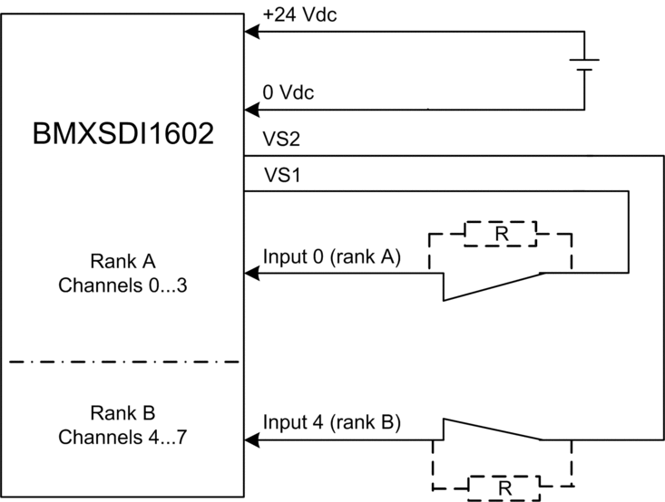
Inputs 0...3 from Rank A are used with Inputs 4...7 from Rank B.
Inputs 0...3 from Rank B are used with Inputs 4...7 from Rank A.
| WARNING | |
|---|---|
In this example, if internal power is supplied via:
VS1, use channels 0...3 ranks A & B.
VS2, use channels 4...7 ranks A & B.
In this design, you could use the
S_EQUIVALENTfunction block to manage the two input signals.Consider adding a Shottky diode to the input loop, between the sensor and the input point, to reduce the likelihood that a short circuit to 24 Vdc condition on one channel might cause the same condition on an adjacent channel.
Wiring diagnostic with single sensor connected to two inputs, using power from the VS pin:
Condition |
Detectable? |
Typical Detection Time |
|---|---|---|
Open (or cut) wire1 |
Yes |
< 10 ms |
Short circuit to the 0 V ground |
Yes |
|
Short circuit to the 24 Vdc1 |
Yes |
< 1 s |
Crossed circuits between two channels |
Yes |
|
1. This diagnostic function is performed if enabled in the module tab in Control Expert. |
||
| WARNING | |
|---|---|
| WARNING | |
|---|---|
Acquisition of the same process variable using two separated sensors (linked mechanically or not) using external power:
Wiring diagnostic with single sensor connected to two inputs, using external power:
Condition |
Detectable? |
Typical Detection Time |
|---|---|---|
Open (or cut) wire1 |
Yes |
< 10 ms |
Short circuit to the 0 V ground |
Yes |
|
Short circuit to the 24 Vdc1 |
No |
– |
Crossed circuits between two channels |
No |
|
1. This diagnostic function is performed if enabled in the module tab in Control Expert. |
||
| WARNING | |
|---|---|
| WARNING | |
|---|---|
Cat4/PLe with High Availability
Wiring scheme with single-channel connection of two redundant single-channel sensors using Vs:
The following example presents two redundant single-channel sensors (which may or may not be mechanically linked), each wired to two input points on two different input modules, with power supplied by the monitored VS power supply:
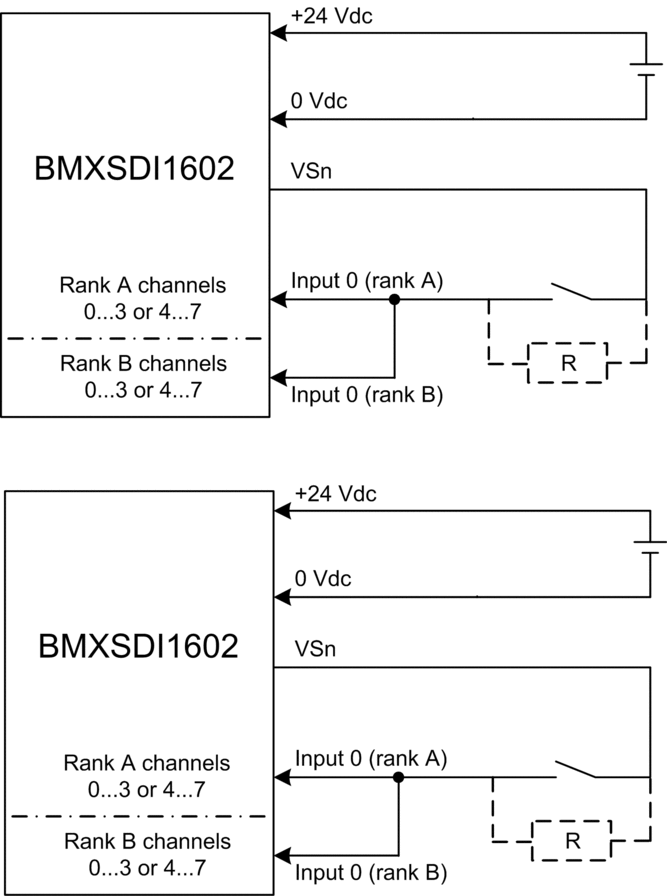
In this example, if internal power is supplied via:
VS1, use channels 0...3 ranks A & B.
VS2, use channels 4...7 ranks A & B.
In this design, you could use the
S_EQUIVALENTandS_DIHAfunction blocks to manage the four input signals.Consider adding a Shottky diode to the input loop, between the sensor and the input point, to reduce the likelihood that a short circuit to 24 Vdc condition on one channel might cause the same condition on an adjacent channel.
Wiring diagnostic with single sensor connected to two inputs, using power from the VS pin:
Condition |
Detectable? |
Typical Detection Time |
|---|---|---|
Open (or cut) wire1 |
Yes |
< 10 ms |
Short circuit to the 0 V ground |
Yes |
|
Short circuit to the 24 Vdc1 |
Yes |
< 1 s |
Crossed circuits between two channels |
Yes |
|
1. This diagnostic function is performed if enabled in the module tab in Control Expert. |
||
| WARNING | |
|---|---|
Wiring scheme with single-channel connection of two redundant single-channel sensors using external power:
Wiring diagnostic with single sensor connected to two inputs, using external power:
Condition |
Detectable? |
Typical Detection Time |
|---|---|---|
Open (or cut) wire1 |
Yes |
< 10 ms |
Short circuit to the 0 V ground |
Yes |
|
Short circuit to the 24 Vdc1 |
No |
– |
Crossed circuits between two channels |
No |
|
1. This diagnostic function is performed if enabled in the module tab in Control Expert. |
||
| WARNING | |
|---|---|
| WARNING | |
|---|---|
Non-equivalent sensor (linked mechanically or not) connected on 2 non-equivalent inputs of two different modules using Vs:
The following example presents two pair of redundant non-equivalent sensors (which may or may not be mechanically linked), each wired to a single input point on two different input modules (two on each module), with power supplied by the monitored VS power supply:
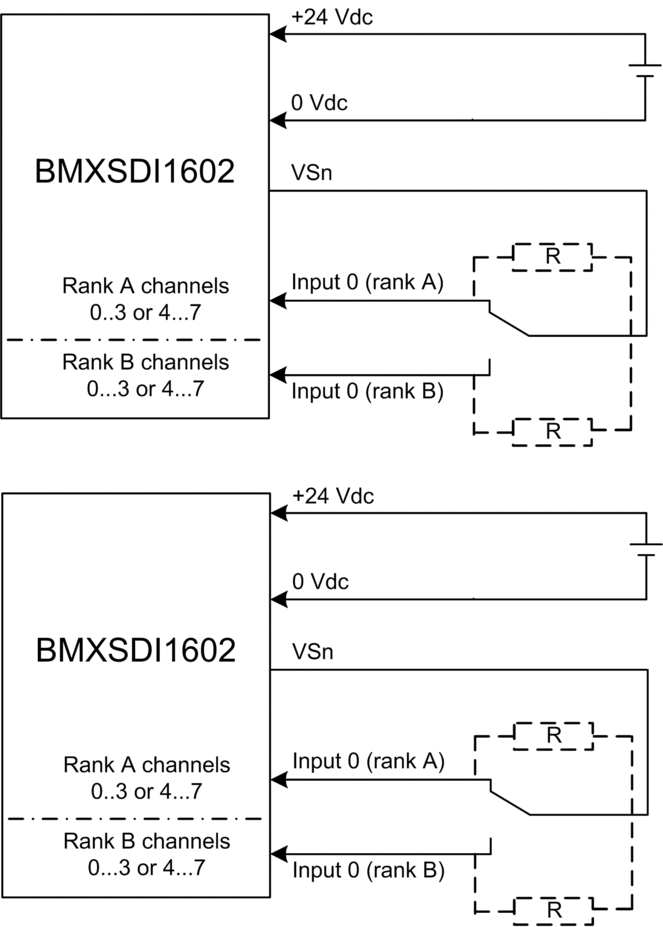
In this example, if internal power is supplied via:
VS1, use channels 0...3 ranks A & B.
VS2, use channels 4...7 ranks A & B.
In this design, you need to use the
S_ANTIVALENTandS_DIHAfunction blocks to manage the four input signals.S_ANTIVALENTto perform 1oo2 evaluation of two pairs of values coming from both sensors connected to the same module.S_DIHAto manage the high availability feature.
Consider adding a Shottky diode to the input loop, between the sensor and the input point, to reduce the likelihood that a short circuit to 24 Vdc condition on one channel might cause the same condition on an adjacent channel.
Because the sensor is supplied power internally via a VS pin, the following channel wiring diagnostics apply:
Condition |
Detectable? |
Typical Detection Time |
|---|---|---|
Open (or cut) wire1 |
Yes |
< 10 ms |
Short circuit to the 0 V ground |
Yes |
|
Short circuit to the 24 Vdc1 |
Yes |
< 1 s |
Crossed circuits between two channels |
Yes |
|
1. This diagnostic function is performed if enabled in the module tab in Control Expert. |
||
| WARNING | |
|---|---|
Non-equivalent sensor (linked mechanically or not) connected on 2 non-equivalent inputs of two different modules using external power:
| WARNING | |
|---|---|
| WARNING | |
|---|---|


