Introduction
The BMXSDI1602 digital input module presents 16 inputs in two groups of 8 inputs. The first group consists of inputs 0...3 (rank A & B), the second group consists of inputs 4...7 (rank A & B). There is no isolation between these two groups.
Power can be provided to the sensors either directly from the external power supply, or internally via the VS1 and VS2 power supplies. Each design is presented, below.
Terminal Blocks
You can use the following Schneider Electric 20-point terminal blocks to fit the 20 pin connector on the front of the module:
screw clamp terminal block BMXFTB2010
age clamp terminal block BMXFTB2000
spring type terminal block BMXFTB2020
Process Power Supply
A 24 Vdc protected extra low voltage (SELV/PELV) overvoltage category II process power supply is required. Schneider Electric recommends a power supply that does not automatically restore power after a power interruption.
| DANGER | |
|---|---|
Fuse
A fast blow fuse is required to help protect the external power supply against short-circuit and over voltage conditions.
| NOTICE | |
|---|---|
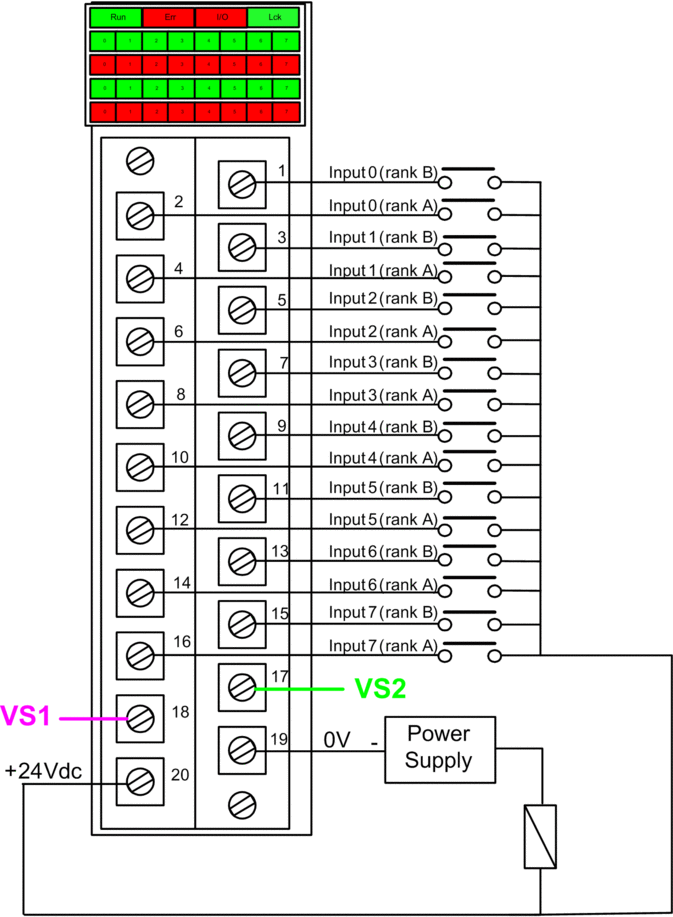
Wiring Connector: Sensors Supplied with External Power
In the following design, the sensors are powered directly from an external power supply:

power supply: 24Vdc
fuse: fast blow fuse of 0.5A
A cut (or open) wire condition (if enabled for the channel in Control Expert).
A short circuit to ground condition.
However, in this design, the module does not detect:
A short circuit to 24 Vdc condition.
A cross circuit condition with other wiring input.
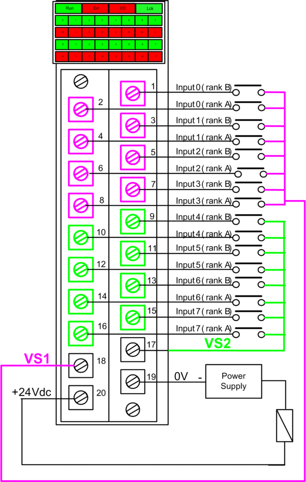
Wiring Connector: Sensors Supplied with Internal VS Power
In the following design, sensors for channels 0...3 are supplied by the monitored VS1 power supply and sensors for channels 4...7 are supplied by the monitored VS2 power supply:

If you use this design, apply internal power to the channel groups as follows:
Use VS1 to supply power to channels 0...3 (rank A and B).
Use VS2 to supply power to channels 4...7 (rank A and B).
A short circuit to 24 Vdc condition (if enabled for the channel in Control Expert).
A cross circuit condition with other wiring input.
A cut (or open) wire condition (if enabled for the channel in Control Expert).
A short circuit to ground condition.
Mapping Inputs to Connector Pins and Control Expert Channels
The following provides a description of each pin on the BMXSDI1602 input module, and maps each pin to the channel for that pin as it appears in the channel tab for the module in Control Expert Safety:
Control Expert Channel |
Pin Description |
Pin Number on Terminal Block |
Pin Description |
Control Expert Channel |
|
|---|---|---|---|---|---|
0 |
Input 0 (rank A) |
2 |
1 |
Input 0 (rank B) |
8 |
1 |
Input 1 (rank A) |
4 |
3 |
Input 1 (rank B) |
9 |
2 |
Input 2 (rank A) |
6 |
5 |
Input 2 (rank B) |
10 |
3 |
Input 3 (rank A) |
8 |
7 |
Input 3 (rank B) |
11 |
4 |
Input 4 (rank A) |
10 |
9 |
Input 4 (rank B) |
12 |
5 |
Input 5 (rank A) |
12 |
11 |
Input 5 (rank B) |
13 |
6 |
Input 6 (rank A) |
14 |
13 |
Input 6 (rank B) |
14 |
7 |
Input 7 (rank A) |
16 |
15 |
Input 7 (rank B) |
15 |
– |
VS1 Power Supply |
18 |
17 |
VS2 Power Supply |
– |
– |
24 Vdc Process Power Supply |
20 |
19 |
24 Vdc Process Power Supply |
– |


