|
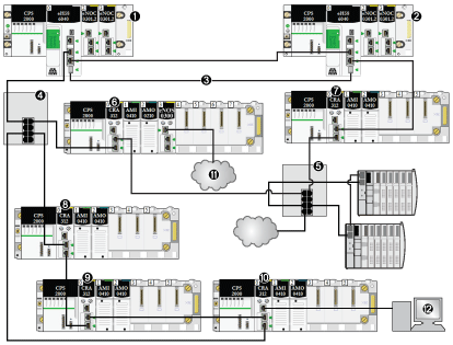
Application Response Time Example
|
|
|
Original instructions
|

1The primary rack includes an M580 CPU.
2The secondary rack includes an M580 CPU.
3The Hot Standby ports on the primary and standby CPUs are linked.
4A DRS on the main ring supports an RIO sub-ring.
5A DRS on the main ring supports a DIO sub-ring and a DIO cloud.
6, 7RIO drops on the main ring include BM•CRA312•0 X80 EIO adapter modules.
8, 9, 10An RIO drop on an RIO sub-ring includes a BM•CRA312•0 X80 EIO adapter module.
11A DIO cloud is connected to a BMENOS0300 network option switch module in an RIO drop.
12An HMI device is connected to a BM•CRA312•0 X80 EIO adapter module in an RIO drop.
|
Parameter
|
Maximum value (ms)
|
Comments
|
|---|---|---|
|
CRA drop process time (CRA_Drop_Process)
|
4.4
|
The sum of CRA input scan time and queue delay.
|
|
CRA input RPI (RPI)
|
—
|
Default = 0.5 * CPU period.
|
|
network input time (Network_In_Time)
|
(0.078 * 10) = 0.780
|
The hop count is 10 from the CPU with Ethernet I/O scanner service in the local rack (1) to the BM•CRA312•0 X80 EIO adapter module in the RIO drop (8).
hop sequence: 8, 9, 10, 4 (x2), 6, 5 (x2), 7, 2, 1 (Count each DRS [4, 5] as two devices when you calculate the capacity of your main-ring.)
|
|
network input jitter (Network_In_Jitter)
|
((0.078 * 5) +
|
RIO: The value 5 represents the number of BM•CRA312•0 modules plus the number of CPUs based on a packet size of 800 bytes.
|
|
(0.128 * 2))
|
DIO: The value 2 represents the number of packets from distributed equipment based on a packet size of 1500 bytes.
|
|
|
= 0.646
|
||
|
CPU input jitter (CPU_In_Jitter)
|
(1 + (0.07 * 5)) = 1.35
|
Read packets from the distributed devices attached to DRS 5 and the BM•CRA312•0 modules (6, 7, 9, 10).
|
|
CPU scan time (CPU_Scan)
|
2 * CPU_Scan
|
User defined, based on application.
|
|
CPU output jitter (CPU_Out_Jitter)
|
(1 + (0.07 * 5)) = 1.35
|
CPU Ethernet I/O service internal queue delay (owing to BM•CRA312•0 modules)
|
|
network output time (Network_Out_Time)
|
(0.078 * 10) = 0.780
|
See comment above for Network_In_Time.
|
|
network output jitter (Network_Out_Jitter)
|
(0.128 * 1) = .128
|
Owing to distributed devices.
|
|
BM•CRA312•0 drop process time (CRA_Drop_Process)
|
4.4
|
The sum of the BM•CRA312•0 X80 EIO adapter module (6) output scan time and queue delay.
|
|
For an explanation of each parameter, refer to the topic ART Computation Parameters.
|
||