|
|
Original instructions
|

|
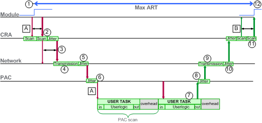
A: missed input scan
|
6: CPU input jitter
|
|
B: missed output scan
|
7: operation of application logic (1 scan)
|
|
1: input turns ON
|
8: CPU output jitter
|
|
2: CRA drop processing time
|
9: network delay
|
|
3: CRA input request packet interval (RPI) rate
|
10: network jitter
|
|
4: network delay
|
11: CRA drop processing time
|
|
5: network jitter
|
12: output applied
|
|
ID
|
Parameter
|
Maximum value (ms)
|
Description
|
|
|---|---|---|---|---|
|
2
|
CRA drop process time (CRA_Drop_Process)
|
4.4
|
The sum of CRA input scan time and queue delay
|
|
|
3
|
CRA input RPI (RPI)
|
ľ
|
CPU task. Default = 0.5 * CPU period if MAST is in periodic mode. If MAST is in cyclic mode, the default value is watchdog/4).
|
|
|
4
|
network input time2 (Network_In_Time)
|
2.496 (0.078 * 32)
NOTE: The value 2.496 ms is based upon a packet size of 800 bytes and 32 hops1. |
The product of (network delay based on I/O packet size) * (the number of hops1 the packet travels). The network delay component can be estimated as follows:
|
|
|
I/O packet size (bytes):
|
Estimated network delay (μs):
|
|||
|
128
|
26
|
|||
|
256
|
35
|
|||
|
400
|
46
|
|||
|
800
|
78
|
|||
|
1200
|
110
|
|||
|
1400
|
127
|
|||
|
5
|
network input jitter (Network_In_Jitter)
|
6.436 ((30 * 0.078) + (32 * 0.128))
NOTE: This value is based on a packet size of 800 bytes for RIO drops and 1500 bytes for DIO traffic. |
formula: ((number of RIO drops) * (network delay)) + ((number of distributed equipment hops1) * network delay)
|
|
|
6
|
CPU input jitter (CPU_In_Jitter)
|
5.41 (1 + (.07 * 63))
|
CPU input queue delay (owing to RIO drops and DIO traffic)
|
|
|
7/8
|
CPU scan time (CPU_Scan)
|
ľ
|
This is the user defined Control Expert scan time, which can be either fixed or cyclic.
|
|
|
9
|
CPU output jitter (CPU_Out_Jitter)
|
2.17 (1 + (0.07 * 31))
|
CPU output queue delay.
|
|
|
10
|
network output time2 (Network_Out_Time)
|
2.496
|
See calculation above for Network_In_Time.
|
|
|
11
|
network output jitter (Network_Out_Jitter)
|
4.096 (32 * 0.128)
|
Calculate in the same manner as Network_In_Jitter without I/O frames from RIO drops.
|
|
|
12
|
CRA drop process time (CRA_Drop_Process)
|
4.4
|
The sum of CRA queue delay and output scan time.
|
|
|
1. A hop is a switch that a packet passes through on the path from a source (transmitting) device to a destination (receiving) device. The total number of hops is the number of passthrough switches along the path.
2. Network input and output times may be increased when optical fiber is used.
increase = total length of fiber cables * 0.0034áms/km
|
||||