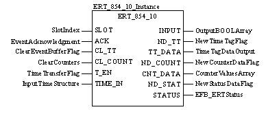
|
Description
|
|
|
Original instructions
|


CAL ERT_854_10_Instance (SLOT:=SlotIndex,
    ACK:=EventAcknowledgment, CL_TT:=ClearEventBufferFlag,
    CL_COUNT:=ClearCounters, T_EN:=TimeTransferFlag,
    TIME_IN:=InputTimeStructure, INPUT=>OutputBoolArray,
    ND_TT=>NewTimeTagFlag, TT_DATA=>TimeTagDataOutput,
    ND_COUNT=>NewCounterDataFlag,
    CNT_DATA=>CounterValuesArray,
    ND_STAT=>NewStatusDataFlag, STATUS=>EFB_ERTStatus)
ERT_854_10_Instance (SLOT:=SlotIndex,
    ACK:=EventAcknowledgment, CL_TT:=ClearEventBufferFlag,
    CL_COUNT:=ClearCounters, T_EN:=TimeTransferFlag,
    TIME_IN:=InputTimeStructure, INPUT=>OutputBoolArray,
    ND_TT=>NewTimeTagFlag, TT_DATA=>TimeTagDataOutput,
    ND_COUNT=>NewCounterDataFlag,
    CNT_DATA=>CounterValuesArray,
    ND_STAT=>NewStatusDataFlag, STATUS=>EFB_ERTStatus) ;
|
Parameter
|
Data type
|
Meaning
|
|---|---|---|
|
SLOT
|
The Slot index is assigned to the EFB ERT_854_10 from either the QUANTUM EFB or DROP EFB and contains the configured input and output references (%IW and %MW)
|
|
|
ACK
|
Event confirmation: Setting ACK signals that the user is ready to receive the next result and deletes the TT_DATA marker. If ACK remains set "continuous operation" appears.
|
|
|
CL_TT
|
BOOL
|
Delete the ERT event FIFO buffer by setting CL_TT. Saving of events is blocked until the CL_TT is reset to 0.
|
|
CL_COUNT
|
BOOL
|
Delete all ERT counters by setting CL_COUNT. Counting is interrupted until CL_COUNT is reset to 0.
|
|
T_EN
|
BOOL
|
Enables a time transfer, e.g. from the ESI using TIME_IN, if set
|
|
TIME_IN
|
DPM_Time
|
Structure of the ESI, e.g. input time through time synchronization of the ERT (carries the edge controlled time synchronization in the Sync element)
|
|
Parameter
|
Data type
|
Meaning
|
|---|---|---|
|
INPUT
|
BoolArr32
|
Output field for all 32 digital inputs in BOOL format
(also provided in the form of word references as %IWx and %IWx+1)
|
|
ND_TT
|
BOOL
|
Marker, new data in TT_DATA structure: remains set until user confirmation with ACK
|
|
TT_DATA
|
ERT_10_TTag
|
Event message output structure with time mark. An event is held and ND_TT is set to 1 until there is a user enable with ACK = 1.
|
|
ND_COUNT
|
BOOL
|
Marker, new counter data in CNT_DATA Structure: The value 1 is set for only one cycle and is not recorded.
|
|
CNT_DATA
|
UDIntArr32
|
Output field for 32 counter values is overwritten after the EFB has received a complete set of consistent counter values (configured as: 8, 16, 24, or 32).
|
|
ND_STAT
|
BOOL
|
Marker; new status data in STATUS word: The value 1 is set for only one cycle and is not acknowledged.
|
|
STATUS
|
Output word for EFB/ERT status (for internal details see Data Flow)
|
|
Element
|
Element type
|
Meaning
|
|---|---|---|
|
Sync
|
BOOL
|
Clock synchronization with positive edge (hourly or on command)
|
|
Ms_Lsb
|
Time in milliseconds (low value byte)
|
|
|
Ms_Msb
|
BYTE
|
Time in milliseconds (high value byte)
|
|
Min
|
BYTE
|
Time invalid / minutes
|
|
Hour
|
BYTE
|
Summer time / hours
|
|
Day
|
BYTE
|
Day of the week / Day in the month
|
|
Mon
|
BYTE
|
Month
|
|
Year
|
BYTE
|
Year
|
|
Element
|
Element type
|
Meaning
|
|---|---|---|
|
User
|
BYTE
|
Complete time / user number [module number]
|
|
INPUT
|
BYTE
|
Event set type / No. of the first input
|
|
In
|
BYTE
|
Event data: 1, 2 or 8 administered positions
|
|
Ms_Lsb
|
BYTE
|
Time in milliseconds (low value byte)
|
|
Ms_Msb
|
BYTE
|
Time in milliseconds (high value byte)
|
|
Min
|
BYTE
|
Time invalid / minutes
|
|
Hour
|
BYTE
|
Summer time / hours
|
|
Day
|
BYTE
|
Day of the week / Day of the month
|
|
Base
|
Lower limit
|
Upper limit
|
|---|---|---|
|
Hexadecimal
|
16#0
|
16#FFFF
|
|
Octal
|
8#0
|
8#177777
|
|
Binary
|
2#0
|
2#1111111111111111
|
|
Data
|
Representation in one of the bases
|
|---|---|
|
0000000011010011
|
16#D3
|
|
1010101010101010
|
8#125252
|
|
0000000011010011
|
2#11010011
|