|
P890 and P892 Switch Settings for the Drop Address
|
|
|
(Original Document)
|

|
Switches
|
Functions
|
|---|---|
|
For P890 and P892
1-6
|
drop/port address 1-32 binary form
|
|
For P890 ONLY
7-8
|
not used, set to left
|
|
For P892 ONLY
7
8
|
hand shaking for port 1
hand shaking for port 2
L = Data Terminal Ready/Data Set Ready
R = Xon/Xoff
|
|
Switches
|
|||||||
|---|---|---|---|---|---|---|---|
|
1
|
2
|
3
|
4
|
5
|
6
|
||
|
Drop Address
|
Port Number
For P892 ONLY
|
||||||
|
L
|
L
|
L
|
L
|
L
|
L
|
1
|
1,2
|
|
R
|
L
|
L
|
L
|
L
|
L
|
2
|
3,4
|
|
L
|
R
|
L
|
L
|
L
|
L
|
3
|
5,6
|
|
R
|
R
|
L
|
L
|
L
|
L
|
4
|
7,8
|
|
L
|
L
|
R
|
L
|
L
|
L
|
5
|
9,10
|
|
R
|
L
|
R
|
L
|
L
|
L
|
6
|
11,12
|
|
L
|
R
|
R
|
L
|
L
|
L
|
7
|
13,14
|
|
R
|
R
|
R
|
L
|
L
|
L
|
8
|
15,16
|
|
L
|
L
|
L
|
R
|
L
|
L
|
9
|
17,18
|
|
R
|
L
|
L
|
R
|
L
|
L
|
10
|
19,20
|
|
L
|
R
|
L
|
R
|
L
|
L
|
11
|
21,22
|
|
R
|
R
|
L
|
R
|
L
|
L
|
12
|
23,24
|
|
L
|
L
|
R
|
R
|
L
|
L
|
13
|
25,26
|
|
R
|
L
|
R
|
R
|
L
|
L
|
14
|
27,28
|
|
L
|
R
|
R
|
R
|
L
|
L
|
15
|
29,30
|
|
R
|
R
|
R
|
R
|
L
|
L
|
16
|
31,32
|
|
L
|
L
|
L
|
L
|
R
|
L
|
17
|
N/A
|
|
R
|
L
|
L
|
L
|
R
|
L
|
18
|
N/A
|
|
L
|
R
|
L
|
L
|
R
|
L
|
19
|
N/A
|
|
R
|
R
|
L
|
L
|
R
|
L
|
20
|
N/A
|
|
L
|
L
|
R
|
L
|
R
|
L
|
21
|
N/A
|
|
R
|
L
|
R
|
L
|
R
|
L
|
22
|
N/A
|
|
L
|
R
|
R
|
L
|
R
|
L
|
23
|
N/A
|
|
R
|
R
|
R
|
L
|
R
|
L
|
24
|
N/A
|
|
L
|
L
|
L
|
R
|
R
|
L
|
25
|
N/A
|
|
R
|
L
|
L
|
R
|
R
|
L
|
26
|
N/A
|
|
L
|
R
|
L
|
R
|
R
|
L
|
27
|
N/A
|
|
R
|
R
|
L
|
R
|
R
|
L
|
28
|
N/A
|
|
L
|
L
|
R
|
R
|
R
|
L
|
29
|
N/A
|
|
R
|
L
|
R
|
R
|
R
|
L
|
30
|
N/A
|
|
L
|
R
|
R
|
R
|
R
|
L
|
31
|
N/A
|
|
R
|
R
|
R
|
R
|
R
|
L
|
32
|
N/A
|
|
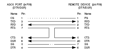
Pin Number
|
Designation
|
|---|---|
|
1
|
Chassis Ground (CG)
|
|
2
|
Receive (RXD)
|
|
3
|
Transmit (TXD)
|
|
4
|
Data Terminal Ready (DTR)
|
|
5
|
Signal Ground (SG)
|
|
6
|
Data Set Ready (DSR)
|
|
7
|
Request to Send (RTS)
|
|
8
|
Clear to Send (CTS)
|
|
9
|
No Connection (N.C.)
|
