|
J890 and J892 Installation and Connection
|
|
|
(Original Document)
|
|
Step
|
Action
|
|---|---|
|
1
|
Turn off the power to the I/O housing.
|
|
2
|
If you are installing a J892, make sure that SW7 on the ASCII communications DIP switch pack is set to the 0 position (on-line).
|
|
3
|
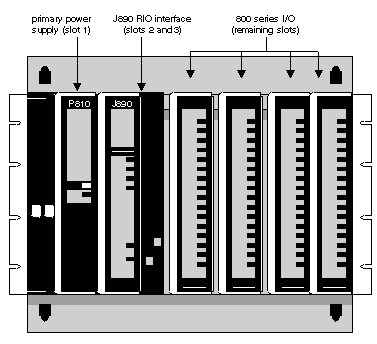
Insert the Interface module in slots 2 and 3 of the primary housing (directly to the right of the power supply unit). Press the module firmly to ensure that it is seated properly.
Position of a J890 interface module in a primary I/O housing.
 |
|
4
|
Tighten the two captive screws located at the top and bottom of the interface module.
|
|
Step
|
Action
|
|---|---|
|
1
|
I/O drop malfunction
Do not disconnect the drop cable while the system is running; disconnecting can cause other I/O drops to malfunction.
|
|
2
|
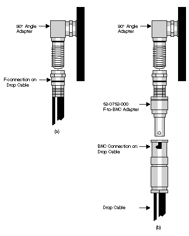
a: If the drop cable connection is a F connector nut, install it directly onto an RIO cable port using a 7/16 in open-end wrench-finger tightening is not sufficient (see Figure below (a))
b: If the drop cable connection is a BNC connector nut, use a Modicon 52-0752-000 F-to-BNC adapter to make the RIO drop connection (see Figure below (b))
 |
|
3
|
If you are installing a J892 for ASCII device support, connect the ASCII device cables to the ASCII ports at this time.
|
|
4
|
Apply power to the I/O housing. The I/O drop is ready for checkout; refer to Appendix B for diagnostic messages provided by the LEDs on the J890/J892 front panels.
Note: For a complete discussion of planning and installing an RIO drop, refer to the Remote I/O System Planning Guide (GM-0984-RIO).
|