|
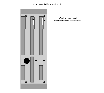
J892 DIP Switch Settings for ASCII Devices
|
|


|
(Original Document)
|
|
J892 DIP Switch Settings for ASCII Devices
|
|
|
(Original Document)
|
|
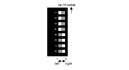
Switches
|
ASCII Communication Function
|
|---|---|
|
1
|
RS-232C handshaking for the bottom ASCII port
1 = Data terminal ready/hardware handshake
0 = XON/XOFF
|
|
2
|
RS-232C handshaking for the top ASCII port
1 = Data terminal ready
0 = XON/XOFF
|
|
3 ... 6
|
Port address 1 - 32
Device addressing in pairs
|
|
7
|
Continuous confidence test mode*
1 = Local diagnostic (J892 will not communicate when set to 1 position (left))
0 = On-line (Normal setting)
|
|
8
|
Not used, always set in the 0 position (right)
|
|
Switches
|
||||
|---|---|---|---|---|
|
3
|
4
|
5
|
6
|
|
|
ASCII ports address
|
||||
|
1, 2
|
0
|
0
|
0
|
0
|
|
3, 4
|
1
|
0
|
0
|
0
|
|
5, 6
|
0
|
1
|
0
|
0
|
|
7, 8
|
1
|
1
|
0
|
0
|
|
9, 10
|
0
|
0
|
1
|
0
|
|
11, 12
|
1
|
0
|
1
|
0
|
|
13, 14
|
0
|
1
|
1
|
0
|
|
15, 16
|
1
|
1
|
1
|
0
|
|
17, 18
|
0
|
0
|
0
|
1
|
|
19, 20
|
1
|
0
|
0
|
1
|
|
21, 22
|
0
|
1
|
0
|
1
|
|
23, 24
|
1
|
1
|
0
|
1
|
|
25, 26
|
0
|
0
|
1
|
1
|
|
27, 28
|
1
|
0
|
1
|
1
|
|
29, 30
|
0
|
1
|
1
|
1
|
|
31, 32
|
1
|
1
|
1
|
1
|
