There are two ways to configure the module to accept current inputs. With eight differential current/voltage inputs the module is called the B875-111. With sixteen single-ended current/voltage inputs the module is called the B877-111.
B875-111 field connections
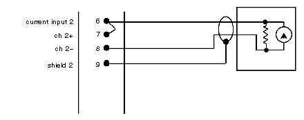
When configuring the B875-111 for eight differential current inputs, note the channels that will receive these inputs. Current inputs are selected by placing a jumper on the field connector between the positive voltage input and the current input terminal for the appropriate channel. For example, if channel 2 is to receive a current input, a jumper must be made between terminal #7 (CH2) and terminal #6 current input CH2), as shown on the following illustration.
The following illustration represents the simplified schematic diagram for the B875111 module.
B875111 analog input module, current input dxample drawing
NOTE: DIP switch accessibility
DIP switches accessible through the side cover are not used in differential mode and should be left in the factory-installed voltage input positions.
NOTE: Simultaneous current and voltage inputs can exist under the following conditions:
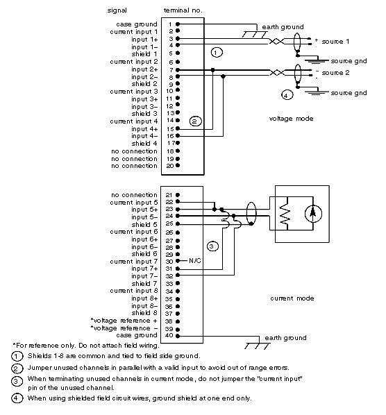
Connect field-side wiring to proper pins on the field connector. Voltage inputs do not require a jumper on the field connector. Refer to the illustration showing the typical field circuit connections, below.
NOTE: Open-circuit voltage inputs may drift either positive or negatively. If open-circuit detection is required, a current input should be used. When using voltage inputs, an open circuit can be detected if a large-value resistor (2 MΩ or greater) is placed at the field connector across the positive (+) and negative (-) inputs. The resistor clamps the channel to a small offset voltage (<100 mV) if the field connections are broken.
Typical field circuit connections with eight differential inputs
B877-111 Field Connections
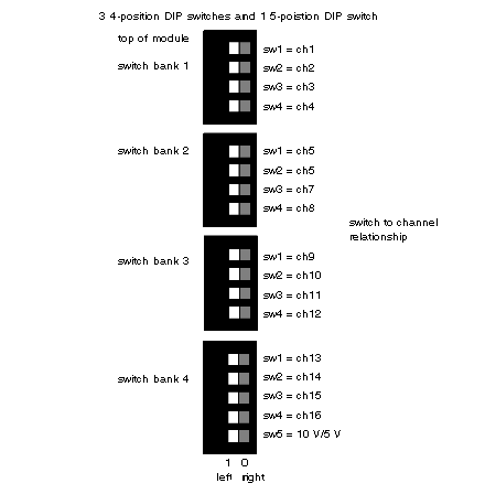
Current inputs are selected by setting the DIP switches accessible through the side cover for each channel to receive an input. The DIP switch places a 250 Ω precision resistor between the positive input and analog returns.
The fifth switch (SW5) on switch bank 4, located on the left side selects the voltage range. The position of this switch must be the same as for module configuration switch SW8, located at the rear of the module.Refer to the label located on the left side of the module, and to the illustration showing the current settings for single-ended inputs (B877) below.
Current settings for single-ended inputs, diagram (B877)
Use the following table to determine the functions for each switch.
|
Switches
|
Functions
|
|
Switch Bank 1
|
Current Inputs
|
|
|
For Channels 14
|
|
|
SW14=Right Side Down
|
|
Switch Bank 2
|
Current Inputs
|
|
|
For Channels 58
|
|
|
SW14=Right Side Down
|
|
Switch Bank 3
|
Current Inputs)
|
|
|
For Channels 9-12
|
|
|
Sw14=Right Side Down
|
|
Switch Bank 4
|
Current Input
|
|
|
For Channels 1316
|
|
|
SW14=Right Side Down
|
|
Switch Bank 5
|
Input Ranges
|
|
|
For 10 V ( V or 010 V): SW5=Left Side Down
|
|
|
For 5 V (All Others): SW5=Right Side Down
|
NOTE: DIP switch accessibility
DIP switches accessible through the side cover are not used in differential mode and should be left in the factory-installed voltage input positions.
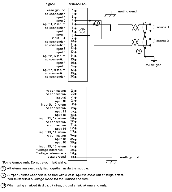
Use the following table to field connect the B77-111 module. Refer to typical field circuit connections, single-ended inputs (B877) diagram, below.
|
Step
|
Action
|
|
1
|
Connect field-side wiring to proper pins on field connector when module is configured for sixteen single-ended inputs.
Note: Open-circuit voltage inputs may drift either positive or negatively. If open-circuit detection is required, a current input should be used. When using voltage inputs, an open circuit can be detected if a large-value resistor (2 MΩ or greater) is placed at the field connector across the positive (+) and negative (-) inputs. The resistor clamps the channel to a small offset voltage (<100 mV) if the field connections are broken.
|
|
2
|
Reinstall any module temporarily removed.
|
|
3
|
When using key pins (provided with housing shipment), install them above and below housing slot selected for this modules installation.
|
|
4
|
Insert module into housing firmly but carefully, seating edge connector in backplane.
|
|
5
|
Secure module to housing using captive slotted mounting screws at top and bottom of module front panel.
|
Typical field circuit connections, single-ended inputs (B877) diagram


