|
B875-102 High Speed Analog Input, Installation
|
|


|
(Original Document)
|
|
B875-102 High Speed Analog Input, Installation
|
|
|
(Original Document)
|
|
Step
|
Action
|
|---|---|
|
1
|
Remove module from shipping box and check for damage. If damage found, contact distributor (or sales person) for correct return procedure.
|
|
2
|
Ensure that power is removed from housing.
|
|
3
|
Configure switch bank A as follows:
|
|
4
|
Configure switch bank B as follows:
|
|
5
|
If using key pins (provided with housing shipment), install them above and below housing slot selected for this module’s installation.
|
|
6
|
Open handle and insert module into housing, firmly seating edge connector in backplane.
|
|
7
|
Secure module using captive mounting screws at top and bottom of module’s front panel.
|
|
8
|
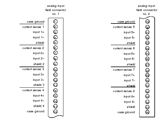
Refer to field connector/input circuit pinout diagram, below. Connect field side wiring to double field connector (located on left side, front edge), laying in cable fan-out as desired.
NOTE: Use field connector wiring sizes AWG—20 inclusive (solid or stranded).
|
|
9
|
If current sense input circuit(s) is being used, jumper appropriate current sense terminal on field connector to corresponding hot input (+) as shown in field connector/input circuit pinout diagram, below.
NOTE: Unused inputs should be terminated to reduce electrical noise and other interference due to floating input lines. Jumper unused voltage and current terminals (including shields) to case ground. Case ground will only be effective if H8XX housing is connected to earth ground. Both ends of the shield cannot be connected to the device and module, unless the device shield is part of the device input circuit, and is not connected internally to the device case ground.
NOTE: If over-range and under-range detection is required, and this detection is causing throughput problems with the unused channels (because they float or spike outside the range) then the unused voltage or current channels at the field connector should be connected in parallel to a valid input channel. As long as the valid channel stays within range, the tied channels will also stay within range.
NOTE: For currents within the range of 4—20 mA, only the valid input requires the inclusion of the 250 Ω resistor.
|
|
10
|
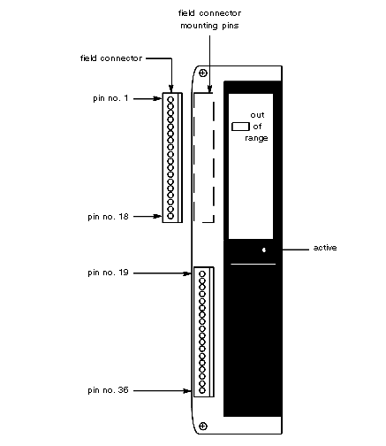
Refer to field connector mounting drawing, below. Mount two wired field connectors on analog module with pin 1 positioned at top and field wiring to left.
|
|
11
|
Close module handle.
|
|
12
|
Turn on power to housing if desired.
NOTE: If an open circuit occurs when operating in the voltage mode, the input may take several seconds to decay to zero, due to the front-end RC network. If open-circuit detection is required, the module should be operated in the current mode. The addition of the 250 Ω resistor forces the RC network to discharge rapidly.
|