B875–102 High Speed Analog Input, Recalibration
(Original Document)
Overview
Since the module is shipped factory-calibrated, it is the designer’s intention that the 10 V reference voltage adjustment will be good for one year. It should be recalibrated annually thereafter.
The following tools are needed to adjust the module’s reference voltage:
NOTE: Field wiring may remain connected during the recalibration procedure, as the module’s working state is not interactive with the reference voltage adjustment. Also, the module does not require warmup to attain temperature.
Recalibration Procedure
Use the following table to recalibrate the module.
Step
Action
1
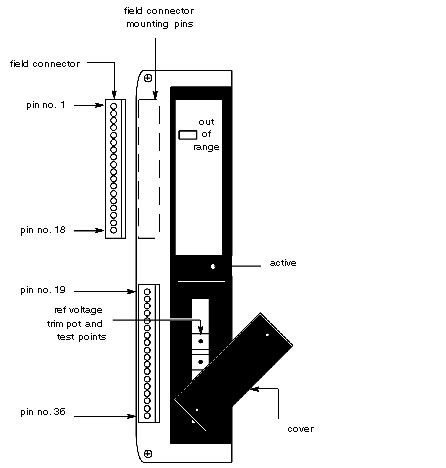
Refer to illustration of reference voltage cover removal, below. Remove reference voltage adjustment cover to gain access to trim pot.
2
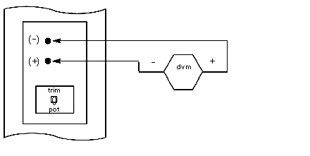
Connect DVM as shown in reference voltage adjustment circuit illustration, below.
3
Adjust reference voltage trim pot for exactly 10.0000 V.
4
Secure trim pot with adhesive.
5
Disconnect voltmeter and secure trim pot access cover.
6
Remove power from equipment housing.
Reference Voltage Cover Removal
Module cover removal
Reference Voltage Adjustment Circuit
Reference voltage adjustment circuit