|
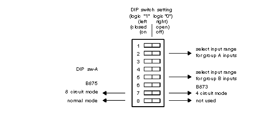
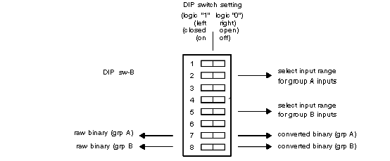
B875–102 High Speed Analog Input, Switch Settings
|
|


|
(Original Document)
|
|
B875–102 High Speed Analog Input, Switch Settings
|
|
|
(Original Document)
|
|
Input Range
|
Switch
|
On
|
Off
|
|---|---|---|---|
|
1 - 5 V
4 - 20 mA
|
A-1
|
X
|
|
|
A-2
|
X
|
|
|
|
A-3
|
X
|
|
|
|
0 - 10 V
|
A-1
|
|
X
|
|
A-2
|
X
|
|
|
|
A-3
|
X
|
|
|
|
0 - 5 V
|
A-1
|
X
|
|
|
A-2
|
|
X
|
|
|
A-3
|
X
|
|
|
|
+/- 10 V
|
A-1
|
|
X
|
|
A-2
|
|
X
|
|
|
A-3
|
X
|
|
|
|
+/- 5 V
|
A-1
|
X
|
|
|
A-2
|
X
|
|
|
|
A-3
|
|
X
|
|
Input Range
|
Switch
|
On
|
Off
|
|---|---|---|---|
|
1 - 5 V
4 - 20 mA
|
A-4
|
X
|
|
|
A-5
|
X
|
|
|
|
A-6
|
X
|
|
|
|
0 - 10 V
|
A-4
|
|
X
|
|
A-5
|
X
|
|
|
|
A-6
|
X
|
|
|
|
0 - 5 V
|
A-4
|
X
|
|
|
A-5
|
|
X
|
|
|
A-6
|
X
|
|
|
|
+/- 10 V
|
A-4
|
|
X
|
|
A-5
|
|
X
|
|
|
A-6
|
X
|
|
|
|
+/- 5 V
|
A-4
|
X
|
|
|
A-5
|
X
|
|
|
|
A-6
|
|
X
|
|
Input Range
|
Switch
|
On
|
Off
|
|---|---|---|---|
|
1 - 5 V
4 - 20 mA
|
A-1
|
X
|
|
|
A-2
|
X
|
|
|
|
A-3
|
X
|
|
|
|
0 - 10 V
|
A-1
|
|
X
|
|
A-2
|
X
|
|
|
|
A-3
|
X
|
|
|
|
0 - 5 V
|
A-1
|
X
|
|
|
A-2
|
|
X
|
|
|
A-3
|
X
|
|
|
|
+/- 10 V
|
A-1
|
|
X
|
|
A-2
|
|
X
|
|
|
A-3
|
X
|
|
|
|
+/- 5 V
|
A-1
|
X
|
|
|
A-2
|
X
|
|
|
|
A-3
|
|
X
|
|
Input Range
|
Switch
|
On
|
Off
|
|---|---|---|---|
|
1 - 5 V
4 - 20 mA
|
A-4
|
X
|
|
|
A-5
|
X
|
|
|
|
A-6
|
X
|
|
|
|
0 - 10 V
|
A-4
|
|
X
|
|
A-5
|
X
|
|
|
|
A-6
|
X
|
|
|
|
0 - 5 V
|
A-4
|
X
|
|
|
A-5
|
|
X
|
|
|
A-6
|
X
|
|
|
|
+/- 10 V
|
A-4
|
|
X
|
|
A-5
|
|
X
|
|
|
A-6
|
X
|
|
|
|
+/- 5 V
|
A-4
|
X
|
|
|
A-5
|
X
|
|
|
|
A-6
|
|
X
|
|
No. of samples averaged
|
Switch
|
On
|
Off
|
|---|---|---|---|
|
1
|
B-1
|
X
|
|
|
B-2
|
X
|
|
|
|
B-3
|
X
|
|
|
|
2
|
B-1
|
|
X
|
|
B-2
|
X
|
|
|
|
B-3
|
X
|
|
|
|
4
|
B-1
|
X
|
|
|
B-2
|
|
X
|
|
|
B-3
|
X
|
|
|
|
8
|
B-1
|
|
X
|
|
B-2
|
|
X
|
|
|
B-3
|
X
|
|
|
|
16
|
B-1
|
X
|
|
|
B-2
|
X
|
|
|
|
B-3
|
|
X
|
|
|
32
|
B-1
|
|
X
|
|
B-2
|
X
|
|
|
|
B-3
|
|
X
|
|
|
64
|
B-1
|
X
|
|
|
B-2
|
|
X
|
|
|
B-3
|
|
X
|
|
No. of samples averaged
|
Switch
|
On
|
Off
|
|---|---|---|---|
|
1
|
B-4
|
X
|
|
|
B-5
|
X
|
|
|
|
B-6
|
X
|
|
|
|
2
|
B-4
|
|
X
|
|
B-5
|
X
|
|
|
|
B-6
|
X
|
|
|
|
4
|
B-4
|
X
|
|
|
B-5
|
|
X
|
|
|
B-6
|
X
|
|
|
|
8
|
B-4
|
|
X
|
|
B-5
|
|
X
|
|
|
B-6
|
X
|
|
|
|
16
|
B-4
|
X
|
|
|
B-5
|
X
|
|
|
|
B-6
|
|
X
|
|
|
32
|
B-4
|
|
X
|
|
B-5
|
X
|
|
|
|
B-6
|
|
X
|
|
|
64
|
B-4
|
X
|
|
|
B-5
|
|
X
|
|
|
B-6
|
|
X
|
|
No. of samples averaged
|
Switch
|
On
|
Off
|
|---|---|---|---|
|
1
|
B-1
|
X
|
|
|
B-2
|
X
|
|
|
|
B-3
|
X
|
|
|
|
2
|
B-1
|
|
X
|
|
B-2
|
X
|
|
|
|
B-3
|
X
|
|
|
|
4
|
B-1
|
X
|
|
|
B-2
|
|
X
|
|
|
B-3
|
X
|
|
|
|
8
|
B-1
|
|
X
|
|
B-2
|
|
X
|
|
|
B-3
|
X
|
|
|
|
16
|
B-1
|
X
|
|
|
B-2
|
X
|
|
|
|
B-3
|
|
X
|
|
|
32
|
B-1
|
|
X
|
|
B-2
|
X
|
|
|
|
B-3
|
|
X
|
|
|
64
|
B-1
|
X
|
|
|
B-2
|
|
X
|
|
|
B-3
|
|
X
|
|
No. of samples averaged
|
Switch
|
On
|
Off
|
|---|---|---|---|
|
1
|
B-4
|
X
|
|
|
B-5
|
X
|
|
|
|
B-6
|
X
|
|
|
|
2
|
B-4
|
|
X
|
|
B-5
|
X
|
|
|
|
B-6
|
X
|
|
|
|
4
|
B-4
|
X
|
|
|
B-5
|
|
X
|
|
|
B-6
|
X
|
|
|
|
8
|
B-4
|
|
X
|
|
B-5
|
|
X
|
|
|
B-6
|
X
|
|
|
|
16
|
B-4
|
X
|
|
|
B-5
|
X
|
|
|
|
B-6
|
|
X
|
|
|
32
|
B-4
|
|
X
|
|
B-5
|
X
|
|
|
|
B-6
|
|
X
|
|
|
64
|
B-4
|
X
|
|
|
B-5
|
|
X
|
|
|
B-6
|
|
X
|
