The data update period is the time taken by the module to present fresh data for each channel. With four input circuits, this period is no more than 2.4 ms; for an eight input circuit configuration, this period is no more than 3.0 ms.
An internal autocalibration process is executed at appropriate times (if necessary) to compensate signal processing for front end drift. The autocalibration function employs feedback mechanisms to adjust the reference voltage to offset gain in the analog to digital converter. Calibration is monitored continuously in the background and adjusted if and when necessary. The following figure shows autocalibration points for all five input ranges. Autocalibration points are indicated by heavy dots on slope line.
The autocalibration process uses the 10 V reference to calibrate the module. The reference voltage is factory preset to exactly 10 volts (zeroed to four places). It should be readjusted in the field once per year.
The input module performs an analog-to-digital conversion of an input analog signal with 12 bit resolution (i.e., 1 part in 4096). This implies that the least significant bit of the output code corresponds to slightly more than 0.024% of full scale.
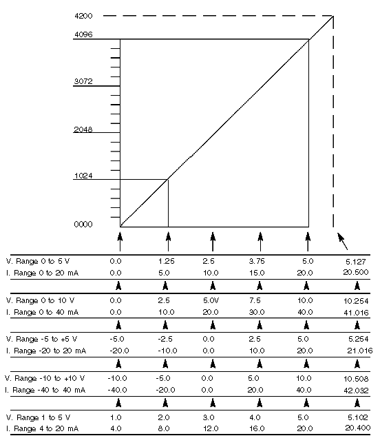
The following illustration is a coarse grain conversion chart for plotting analog input against the equivalent numerical value output to the PC in raw binary format. The example illustrated shows an input voltage of 1.25 V (25% of 5 V FSR) and a numerical count of 1024 (25% of 4200) as projected through the 455 slope line.
Calculate exact values using the following proportional equation:
Where FSR is full scale range for analog input (including bipolar) and FCR is full count range (4200) in a raw binary format.
B875–102 High Speed Analog Input Autocalibration Points—All Ranges
B875–102 Input Signal vs. Output Data (Raw Binary Format)
The module is capable of presenting the digitized data to the PC in either raw binary (RB) or converted binary (CB) format. The bit pattern in each case is different. The format is switch selectable and need not be the same for each group of input circuits. A Modicon programmer will display either type of data in one of three different ways: binary, hexadecimal, or decimal form.
Conversion linearity for this module is 0.05% of full scale–referenced to a straight line drawn through the measured full-scale value and the measured zero point–over the module’s operating temperature range.
Raw Binary (RB) Format After digitizing the input signal, the input module presents data in RB format. In decimal representation, data in RB format must be within the 0 to 4200 range. Normally, a 12--bit device would have an upper data limit of 4095. This analog module has the means of allowing the input to be up to 2% over-range at the same resolution (i.e., the count in raw binary may go up to 4200). In RB format, the data range is the same regardless of the voltage range.
Converted Binary (CB) Format CB is obtained by transforming the RB format within the module. When CB data is viewed by the PC or programmer in decimal mode, it looks like a 4-digit voltmeter (DVM) with no sign or decimal point. In CB for-mat, upper and lower data limits are voltage range dependent. Because of the missing sign, CB format is used only for unipolar voltage ranges.
The following figure shows an example of raw binary output. When a 5 V signal is digitized by the module set for 0 to 10 V range, it produces a converted binary code 0800 hex or 2048 decimal.
Raw Binary Word Format
The following figure shows the conditions in converted binary format which produce 1388 hex or 5000 decimal.
Converted Binary Word Format


