B875–102 High Speed Analog Input, Inputs
(Original Document)
Configuration
Module inputs are configurable in two groups by means of DIP switches.
The following table shows input switch group assignments for the four or eight input circuit configurations.
Configuration
Input Group A
Input Group B
Eight Input circuits
1, 2, 3, 4
5, 6, 7, 8
Four input circuits
1, 2
3, 4
Input Ranges
The following table shows the five input ranges acceptable to each input range group. The module will accept an input as much as 2% FSR above its specified range without going into an over-range condition, but nothing below range.
Voltage range (V)
Corresponding Current Range (mA)
0—5
0—20
0—10
0—40
1—5
4—20
-10—+10
-40—+40
-5—+5
-20—+20
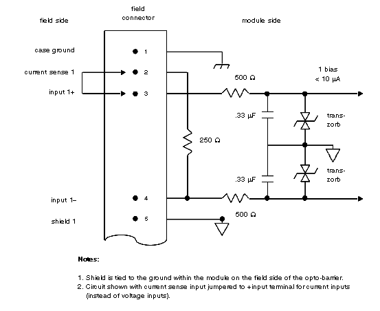
For purposes of determining load and protection considerations for the inputting of field circuits, The following figure is a schematic diagram of the input circuit’s front end. Note the built-in 250 Ω resistor connected to the current input terminal. When the current sense terminal is externally jumpered to the positive input terminal, current input becomes possible for that input regardless of the voltage range selected.
NOTE: The current sense function has been provided specifically for the 4—20 mA current loop applications (1—5 V input range). However, current mode is operable on all ranges.
B875–102 High Speed Analog Input, Input Circuit Front End.