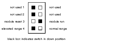
B873-012 and B875-012 Switch Settings and Indicators
(Original Document)
Switch Settings
There is a DIP switch located at the rear of the module. Switches 1, 2 and 4 are not used. Switch 3 can be set to either module reset or module run. It must be set to the module run position for the module to operate. Make sure you set switch 3 before inserting the module into the housing. Refer to the figure below for DIP switch settings.
Indicators
The Active and Over Range indicators are located on the front panel of the module. The Over Range indicator is shared by all of the module's input channels. The module's status can be determined by referring to the table below.
Indicator
State
Condition
Active
on
blinking
off
The module is communicating properly and the PLC is running
The module failed the powerup reference test
The module failed the internal diagnostic test/PLC is not in run mode/communication from PLC to module has failed
Over Range
off
on or blinking
All input are within valid input range
One or more inputs have exceeded the valid input range