The B817–116 (115 Vac) and B817–216 (230 Vac) isolated input modules sense off and on input voltages from its field circuitry, converting them to dc logic levels used in the logic program by a PLC.
The module’s 16 input circuits are individually isolated from one another. As each input circuit uses a neutral return wire, none has a definite relationship to system ground unless established in the user’s field circuitry. The module’s logic circuitry is shielded from radiated signals or interference originating in the field, and its field inputs are optically isolated from the system logic.
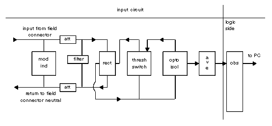
Following is a simplified schematic of the B817–116 (115 Vac) and B817–216 (230 Vac) isolated input modules.
When the voltage exceeds the threshold circuits voltage requirement, current will flow through the threshold switch and opto-isolator via the precision attenuator and the bridge rectifier. The output pulses coupled through the isolator are averaged so that a steady state dc voltage representation of the inner circuit’s on–state condition is sensed by the Ourbus chip (OBS) on the logic side of the module.
The Ourbus output register is set to represent the field on state. As long as the field input status remains true, the module will communicate this status each time it is polled by the PLC.