The B840–108 relay output module converts signals from the 800 series Ourbus to eight independent relay outputs. Each output is capable of driving relays, pilot lamps, or other loads up to 2 A.
The module utilizes eight high–reliability mercury–wetted relays to control the loads. Each of the eight outputs is electrically isolated from the I/O bus and from the other seven outputs by the relay coil. These outputs are capable of switching 100 VA maximum instantaneous power associated with ac or dc loads. Such devices may range from relays and pilot lamps to multiplexed low level analog signals.
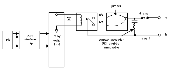
Each output has an RC snubber to protect the mercury wetted contacts from arcing caused by rapid rate of rise of applied voltage from inductive loads upon instantaneous opening of the contacts. The output signals can withstand severe voltage transients that may be encountered in industrial environments—i.e., the voltage transients will not propagate through the relay to the Ourbus, thus protecting all other controller system components from damage. All output circuits are also fused to protect against overload currents.
Simplified Schematic Diagram
Following is a simplified schematic diagram of the B840–108 relay output module.
The module is user–configurable as to setting up for normally–open or normally–closed operation of the relays as described below. You can also optionally configure the RC snubber circuit to remove it when minimal leakage current applications such as data multiplexing are being used.
The logic interface chip samples the eight logic level signals simultaneously from the PLC on each scan and holds these samples to drive the appropriate reed relay coil. Assuming a normally–open jumpered configuration, when the relay coil is energized, the reed relay contacts conduct current from the output A terminal to the output B terminal.
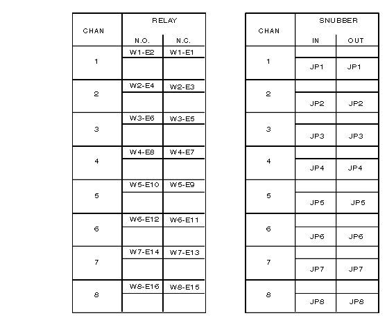
The B840–108 relay module is initially shipped with all 8 channels jumpered for the normally-open configuration with all snubber circuits connected. You may wire any of the channels for either normally-open or normally-closed operation by transferring a wire jumper from one tab to another on the printed circuit board to change from normally-open to normally-closed
The following illustration shows the user wiring configuration for the B840–108 relay module
The snubber circuits are disconnected by removing the (JP1-JP8) appropriate jumper. Refer to the label on the side of the module.

