The B881–001 Latched 24 Vdc input module senses and converts input signals from its field circuitry to a logic level used by PLC. The incoming signal causes the module to latch at the occurrence of the on state and may be considered a latching event. The 24 Vdc, true high latched input module is capable of direct connection to any PLC, true high dc output module (at proper voltage).
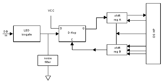
The following illustration shows the B881–001 Latched 24 Vdc input module simplified block diagram
The latching mechanism exists solely to lockout subsequent incoming signals for the time it takes to communicate to the controller that a latching event occurred, receive an acknowledgement, and reset the latch. The latched input module does not affect the users field circuit, drive the controller or communicate information to it other than the fact that a latching event took place.
Signals on the 16-channel inputs are compared to a reference voltage nominally set to 75% of the group supply voltage. An input signal of 500 s minimum pulse width and equal to or exceeding the reference voltage threshold will cause a latched on state for any given channel.An input signal voltage less than 25% of the group supply voltage will result in a system off state.
When the module senses and latches on the leading edge of the true-high, incoming field signal or data bit (DB), it clocks the D-type flip-flop on the low-to-high transition, in effect, capturing the latching event.
The module’s on state is communicated to the controller through shift register (A) and OBS chip via a handshake mechanism. The logic is then returned to the module from the CPU as an inverted signal through shift register (B) where it resets the flip- flop (latch condition) for that channel only. The reset latch is then available for another, low-to-high, event transition. To ensure that the controller has received a latched event, the module actually operates in a user programmed, echoed- data handshake mode. The handshake mechanism requires four to six scans before a new event can be recognized. Total scan time is software-limited to 200 ms maximum and hardware limited to 250 ms maximum.Thus, you should not attempt to record events with a repetition rate greater than one per second unless willing to analyze this actual system and program.
NOTE: Reversal of external load polarity will not cause circuit failure as the module is fused to protect its circuitry against overload currents and accidental polarity reversal.
